$23.95
Download NowSold by snowing on Tradebit
The world's largest download marketplace
3,251,083 satisfied buyers
The world's largest download marketplace
3,251,083 satisfied buyers

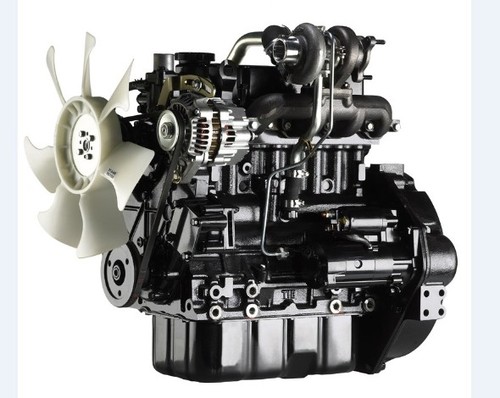
Mitsubishi SL-Series S3L, S3L2, S4L, S4L2 Diesel Engine Service Repair Workshop Manual DOWNLOAD
ENGINES COVERED:
Engine S3L/S3L2
Engine S3L-T/S3L2-T
Engine S4L/S4L2
Engine S4L-T/S4L2-T
Displacement
S3L 1.125 liters (68.7 cu in.)
S3L2 1.318 liters (80.4 cu in.)
S4L 1.500 liters (91.5 cu in.)
S4L2 1.758 liters (107.3 cu in.)
Service Repair Manual Covers:
GENERAL INFORMATION
1 MODEL IDENTIFICATION AND SERIAL NUMBER LOCATION
1.1 Model identification location
1.2 Serial Number Location
2 COMPONENT LOCATION
2.1 S3L/S3L2
2.2 Engine S3L-T/S3L2-T
2.3 S4L/S4L2
2.4 Engine S4L-T/S4L2-T
3 SPECIFICATIONS
OVERHAUL INSTRUCTIONS
4 DETERMINING WHEN TO OVERHAUL THE ENGINE
5 COMPRESSION PRESSURE MEASUREMENT
5.1 Inspection
5.2 Measurement
6 TROUBLESHOOTING
6.1 General
6.2 Engine troubleshooting
6.3 Starting system troubleshooting
7 BASIC PRECAUTIONS FOR DISASSEMBLY AND ASSEMBLY
7.1 Disassembly
7.2 Assembly
DISASSEMBLY
8 PREPARATION FOR DISASSEMBLY
8.1 Engine oil draining
8.2 Coolant draining 1
9 ELECTRICAL SYSTEM
9.1 Starter
9.2 Alternator
10 Cooling System
10.1 Cooling fan removal
10.2 Thermostat case removal
10.3 Water pump assembly removal
11 Fuel System
11.1 Fuel injection pipe removal
11.2 Fuel injection nozzle removal
11.3 Governor assembly removal
11.4 Governor weight removal
11.5 Fuel injection pump removal
12 Lubrication System
12.1 Oil filter removal
12.2 Pressure relief valve removal
12.3 Oil pressure switch removal
13 AIR INLET SYSTEM AND EXHAUST SYSTEM
13.1 Exhaust manifold removal
13.2 Air inlet cover removal
14 CYLINDER HEAD AND VALVE MECHANISM
14.1 Rocker shaft assembly removal
14.2 Rocker shaft disassembly
14.3 Cylinder head bolt removal
14.4 Cylinder head assembly removal
14.5 Valve and valve spring removal
14.6 Valve stem seal removal
15 Timing Gears and Flywheel
15.1 Flywheel removal
15.2 Rear plate removal
15.3 Oil seal case removal
15.4 Tappet removal
15.5 Speedometer driven gear removal
15.6 Crankshaft pulley removal
15.7 Timing gear case removal
15.8 Timing gear backlash measurement
15.9 Idler gear removal
15.10 Camshaft removal
15.11 Fuel injection pump camshaft removal
15.12 Gear removal (when required)
15.13 Oil pump removal
15.14 Front plate removal
16 Cylinder Block, Crankshaft, Pistons and Oil Pan
16.1 Oil pan removal
16.2 Oil screen removal
16.3 Thrust clearance measurement for connecting rod big end
16.4 Connecting rod cap removal
16.5 Piston removal
16.6 End play measurement for crankshaft
16.7 Main bearing cap removal
16.8 Crankshaft removal
16.9 Piston separation from connecting rod
INSPECTION
17 CYLINDER HEAD AND VALVE MECHANISM
17.1 Cylinder head
17.2 Rocker arms and rocker shaft
17.3 Valve springs
17.4 Valve push rods
17.5 Valves, valve guides and valve seats
17.6 Combustion jet replacement
18 TIMING GEARS AND FLYWHEEL
18.1 Camshaft
18.2 Fuel injection pump camshaft
18.3 Tappets
18.4 Idler gear
18.5 Flywheel and ring gear
19 CYLINDER BLOCK, CRANKSHAFT, PISTONS AND OIL PAN
19.1 Pistons, Piston Rings and Piston Pins
19.2 Connecting rods
19.3 Crankshaft
19.4 Cylinder block
ASSEMBLY
20 Cylinder Block, Crankshaft, Pistons and Oil pan
20.1 Main bearing installation
20.2 Crankshaft installation
20.3 Main bearing cap installation
20.4 Side seal installation
20.5 Piston assembling to connecting rod
20.6 Piston ring installation
20.7 Piston and connecting rod installation
20.8 Connecting rod cap installation
20.9 Oil screen installation
20.10 Oil pan installation
21 Timing Gears and Flywheel
21.1 Front plate installation
21.2 Oil pump installation
21.3 Engine turning
21.4 Engine turning
21.5 Camshaft installation
21.6 Idler gear installation
21.7 Timing gear case installation
21.8 Crankshaft pulley nut tightening
21.9 P.T.O. gear installation
21.10 Speedometer driven gear installation
21.11 Tappet installation
21.12 Oil seal case installation
21.13 Rear plate installation
21.14 Flywheel installation
22 CYLINDER HEAD AND VALVE MECHANISM
22.1 Cylinder head bottom face cleaning
22.2 Valve stem seal installation
22.3 Valve spring installation
22.4 Installing valve block
22.5 Cylinder head gasket installation
22.6 Cylinder head installation
22.7 Cylinder head bolt tightening
22.8 Valve push rod installation
22.9 Rocker shaft assembling
22.10 Rocker shaft assembly installation
22.11 Valve clearance adjustment
22.12 Rocker cover installation
23 Air Inlet System and Exhaust System
23.1 Air inlet cover installation
23.2 Exhaust manifold installation
24 Fuel System
24.1 Fuel injection nozzle installation
24.2 Fuel injection pump installation
24.3 Flyweight assembly installation
24.4 Sliding sleeve installation
24.5 Governor assembly installation
24.6 Fuel injection line installation
25 Lubrication system
25.1 Pressure relief valve installation
25.2 Oil filter installation
25.3 Oil pressure switch installation
26 Cooling system
26.1 Water pump installation
26.2 Thermostat installation
26.3 Cooling fan installation
26.4 Thermoswitch and thermounit combination installation
27 Electrical System
27.1 Glow plug installation
27.2 Alternator installation
ELECTRICAL SYSTEM
28 GENERAL
28.1 Specifications (standard)
28.2 Wiring diagrams STARTER
29.1 Disassembly
29.2 Inspection
29.3 Assembly
29.4 Inspection and Testing after Assembly
30 ALTERNATOR
30.1 Disassembly
30.2 Inspection
30.3 Assembly
31 KEY SHUTOFF SYSTEM (ETS solenoid type)
31.1 General
31.2 Cord color (standard)
31.3 Shutoff solenoid installation
31.4 Inspection after assembly
32 KEY SHUTOFF SYSTEM (ETR solenoid type)
32.1 General
32.2 Cord color (standard)
32.3 Shutoff solenoid installation
33 AUTOMATIC GLOW SYSTEM
33.1 General
33.2 Glow timer specification (standard)
33.3 Glow plug relay specifications (standard)
33.4 Glow plug inspection
COOLING SYSTEM
34 GENERAL
34.1 Schematic
34.2 Specifications (standard)
35 INSPECTION
35.1 Water pump
35.2 Thermostat (standard)
35.3 Thermoswitch (standard)
35.4 Thermounit (standard)
LUBRICATION SYSTEM
36 GENERAL
36.1 Schematic
36.2 Specifications
37 INSPECTION
37.1 Oil pump
37.2 Oil pressure switch
37.3 Pressure rel
File Data
This file is sold by snowing, an independent seller on Tradebit.
| File Size | 13 megabytes |
| File Type |