$19.00
Download NowSold by belgreen on Tradebit
The world's largest download marketplace
3,249,779 satisfied buyers
The world's largest download marketplace
3,249,779 satisfied buyers

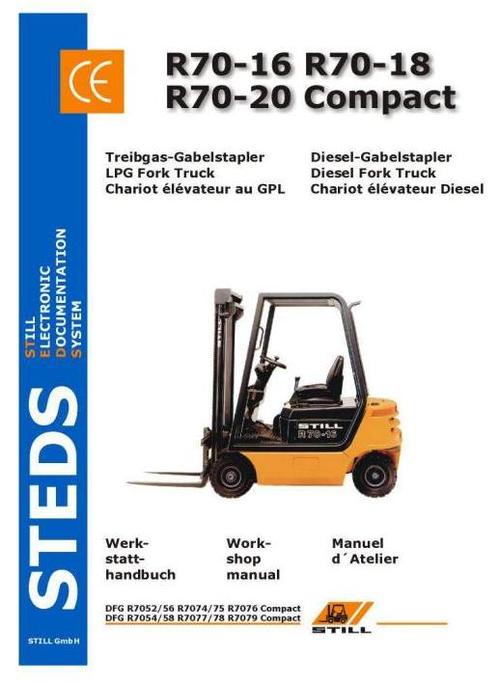
Still Fork Truck R70-16, R70-18, R70-20 Compact: R7052, R7054, R7056, R7058, R7074, R7075, R7076, R7077, R7078, R7079 Workshop Manual
Original factory manuals for Still Forklift Trucks, contains high quality images, circuit diagrams and instructions to help you to operate and repair your truck. All Manuals Printable and contains Searchable Text
Covered models:
R7052
R7054
R7056
R7058
R7074
R7075
R7076
R7077
R7078
R7079
Format: PDF, 305 Pages
Language: English
Contents:
02. Steer Axle
Contents
Technical Data for
Maintenance Service
Mechanical configuration of Steer axle
Steer axle removal
Steer axle installation
Wheel hub -Removal and
Dismantling
Wheel hub- Reassembling and
Installation
Wheel angle stop adjustment
Checking the steering angles
Stub axle -Removal and
Dismantling
Stub axle - Reassembling and
Lubricating the steer axle with
Installation grease
Track rod removal
Track rod installation
Steer cylinder removal
Steer cylinder installation
03. Power Axle
Wheel hub installation
Technical Data for Maintenance Service
Power Axle / Description
Power Axle removal
Power Axle installation
Double reduction gear and differential /
Sectional view
Exploded view
Axle housing installation
Half-shaft (axle shaft) removal
Half-shaft (axle shaft) installation
Wheel hub removal
04. Wheels and tyres
06. Steering
Technical Data for Maintenance
Service
Operation
Adjusting the steering column
Steering control unit
Steering control unit removal
Steering control unit installation
Repairing the steering control unit
Priority valve - Dismantling
Priority valve - Reassembly
Steer cylinder disassembly
Steer cylinder reassembly
07. Brake system
Technical Data for Maintenance Service
Function
Initial adjustment
Parking brake adjustment
Master cylinder
08. Electrical installation
Technical Data for Maintenance Service
Electrical installation
Mechanical configuration
General description
Testing the insulation
Dash panel
Console
Key switch
Travel sender (single pedal control)
Travel sender switch (single pedal control)
Twin pedal control
Warning horn
Brake sender
Parking brake microswitch
Brake fluid level switch
Senders (transmitters) for hyd. functions
Speed sensor
Tachogenerator
Alternator
Servomotor, injection pump
Fuel cut-off solenoid valve
Coolant temperature sensor
Coolant temperature switch
Air filter switch
Batteries
Current sensor
Electric fan for cooling the engine/Spal-/EBM-fan
Throttle positioning solenoid
Fuse holder board
Control circuit fuses
Main circuit fuses
Starter relay
Preheating relay
Relay, solenoid fuel cut-off valve
Controller consisting of:
Traction control circuit
Charge compensating circuit
Power board for traction control
Power board for controlling electric fan 9M5
Replacing the Controller
Calibration
Replacing the Console
FleetManager
FleetManager
Joystick
09. Lighting & instruments
Configuration of lighting equipment
Variants
Equipment level A: Controller, distributing circuit board
Equipment level B: Controller, relay box, distributing circuit board
Equipment level C: Controller, 2 x relay box
Relays
Fuses
Relay box
Distributing circuit board
Parameterization
Parameterization of the additional electrical equipment via the console
10. Hydraulic system
Operation of Lift & Tilt hydraulics
Mechanical configuration/
Fittings instructions
Hydraulic schematic
Operation
Connection block/
Functional description
Hoist/lower functions
Tilting/Hydraulic Ancillary Equipment
Fitting restrictors - tilt valve block/
Block seals
Shuttle valves
Transducer - Operation - Replacement
Mechanical configuration/
Checking for contamination
Operation/Removal & Installation
Hydraulic oil change/Filling capacity/
Breatherfilters
Operation and Maintenance
Assembly
Tube fittings with Captive Seals
Schematic
Legend
11. Electric motor / generator
Drive motor ( R7052/56, R7054/58)
Drive motor, construction
Wiring diagram
Connections
Drive motor removal
Drive motor installation
Drive motor - Dismantling
Drive motor reassembly
Inspecting and changing the motor brushes
Drive motor (AD20 axle)
Drive motor type
Circuit diagram
Position of motor terminals
Removing the drive motor
Fitting the drive motor
Removing the armature
Fitting the armature
Checking and replacing carbon brushes
Speed sensor bearing
Drive motor (exploded drawing)
Drive motor (sectional view)
Generator
Generator, construction
Wiring diagram
Connections
Generator removal
Generator installation
Inspecting and changing the carbon brushes
Generator - Dismantling
Generator reassembly
Thermal monitoring
Brush wear monitoring facility
Forced ventilation
Testing the insulation
General hints
13. Hydraulic auxiliary functions
Technical Data for Maintenance Service
Pressure Regulator Unit I and II -Operation
Pressure Regulator Unit -Relief valve
- Pressure indication
Control valve block
-Fitting restrictors
Pressure limitation for clamps with integral sideshift feature
15. IC engine
Technical data, LP gas engine
Engine features, engine number
Overview
Functional description
Before starting engine
Starting engine
Cold start
Shutting off engine
Note on removing and installing engine
Special tools
Removing, installing tensioning toothed belt
Adjusting tension of V-beltfor alternator
Adjusting tension of V-belt for coolant pump
Replacing crankshaft seal at pulley end
Overview
Removing and installing cylinder head
Checking compression
Repairing valve gear
Replacing camshaft seal
Removing and installing camshaft
Checking hydraulic bucket tappets
General
Oil additives
Changing oil
Renewing the oil filter
Adding oil
Ignition distributor and lubrication system
Removing and installing parts of cooling system
Parts of cooling system, engine side
Radiator
Coolant temperature sensor 6B12
Coolant hose connection diagram
Draining and filling coolant
Safety measures for ignition system
Disassembling transistorised ignition system
Checking and adjusting ignition timing
Checking transistorised ignition (TSZ-H) switch unit
Checking Hall sender
Checking speed limiter
Checking limiting speed
Checking plug connectors, ignition lead and ignition coil
Replacing air filter element
Overview
Functional description
General information
Cleanliness rules
20-25 Mast, Cylinders, Fork carriage, Tilt cylinders
Functional Group 20
Technical Data for Maintenance Service
Mast types / Removal of mast
Telescopic mast
Hi-Lo mast
Triple mast
Lift chain adjustment /Carriage stops
Support rollers
Hoist cylinders 7052/54/56/58
Lowering valve
Line failure safety device
Hoist cylinders 7074 - 79
DemontageAussenzylinder (Hi-Lo, Triplemast)
Demontage Zylinder Telehubgerust
Mittelzylinder Niho / Dreifach
Functional Group 22
Fork carriage removal
Changing the guide roller shafts
Functional Group 25
Tilt cylinder Removal
Tilt cylinder assambling
Mast tilt angle
System diagnosis
File Data
This file is sold by belgreen, an independent seller on Tradebit.
| File Size | 67 megabytes |
| File Type |
