$28.00
Download NowSold by bg-store on Tradebit
The world's largest download marketplace
3,251,194 satisfied buyers
The world's largest download marketplace
3,251,194 satisfied buyers

Linde Truck Type 008: K10, K13 Service Training (Workshop) Manual
Original factory manuals for Linde Forklift Trucks, contains high quality images, circuit diagrams and instructions to help you to operate and repair your truck
Covered models:
K10
K13
Format: PDF, 381 Pages
Language: English
Contents:
A Travel drive
Travel motor
- Travel motor, technical data
- Travel motor connections
Speed sensor
- Speed sensor connections
- Testing the speed sensor
Temperature sensor integrated in the carbon brush yoke
Removing the travel motor
Replacing the travel motor
Removing the gear
Changing the gear oil
Lubricating the bogie bearing
Replacing the drive wheel
Carbon brush monitor
Replacing the carbon brushes
Checking the brush springs
Travel motor maintenance
- General
- Cleaning
- Visual inspection, replacing damaged parts
- Checking the brush unit, replacing the carbon brushes
- Commutator
- Bearings
B Steering system
Block diagram of standard steering
Block diagram of steering controller
Description of steering controller
- Safety tests
- External enable
- Manual steering
- Driving onto the rail guide
- Rail travel
- Guide to potentiometers and LEDs
- Service switch
- Pin assignment
- Main current connections, steering controller
Adjusting the steering
- Adjusting the chain tension
- Replacing the steering chain
- Setting the steering controller potentiometer to the centre position
- Adjusting the turning force of the handwheel
- Setting the retaining force of the handwheel
- End stop
- Adjusting the potentiometer R19/R20
- Adjusting the setpoint potentiometer
- Adjusting the actual value potentiometer
- Setting the maximum steering angle
- Straight-on travel correction
- Rail travel
- Free travel
Steering motor
- Replacing the carbon brushes
- Maintenance
- Steering motor specifications
C Brake system
Automatic end-of-aisle braking with magnetic switches
- General
- Function
- Absolute stop
- Aisle detection
- Errors
- Magnetic switches
- Switching magnet
- Summary of magnetic end-of-aisle braking (ZAG) with rail guidance
- Without absolute and temporary stop
- With absolute and without temporary stop
- With absolute and temporary stop
- Summary of magnetic end-of-aisle braking (ZAG) with inductive automatic steering
- Without absolute and temporary stop
- With absolute and without temporary stop
- With absolute and temporary stop
Automatic end-of-aisle braking with reflective light barriers
- General
- Function
- Errors
- Stop
- Temporary stop
- Absolute stop
- Interlock module 8U40
- Terminals
- Installation of the reflectors in an aisle
- Distance between reflectors
- Summary of ZAG reflexli with rail guidance
- With absolute stop and check
- Summary of ZAG reflexli with inductive automatic steering
- With absolute stop and check
E Assembly
Assembly - vehicle
Removing the load carriage
Assembly - Telescopic load carriage
Assembly - Swivel shift fork
Replacing the idling wheels
- Removal
- Installation
Chains
- general
- Checking the flyer chains
- Chain maintenance
F Cylinders
Cylinder support
Removing the main lift cylinder
Dismantling the main lift cylinder
Removing the additional lift
Removing the additional lift cylinder
Dismantling the additional lift cylinder
Dismantling the pulling cylinder (attachment)
Line break protection type LB-3C
- General
- Valve for full support of the load
Lowering brake valve SB17-C-14
I Inductive automatic steering
- Setting the setpoint potentiometer
- Setpoint potentiometer
- Setting the offset potentiometer for "Straight on forwards and reverse"
to "00"
- Setting the actual value potentiometer
- Actual value potentiometer
- Guide frequency generator
Battery buffer
Commissioning the guide frequency generator
Adapting the output filter to a wire loop
Connecting a wire loop
Technical data
- Mounting and adjusting the aerials
Finding the centre marking for mounting the front aerials
Adjusting the front aerials
Setting the offset potentiometer for "Straight on forwards"
Mounting and adjusting the rear aerial
Setting the offset potentiometer for "Straight on reverse"
-Aerials
- Emergency-stop parameters - General
- Emergency-stop parameter - XE59
- Emergency-stop parameter - XE5B
- Emergency-stop parameter - XE5A
- Emergency-stop parameter - XE5D
- Setting the steering angle limitation
Switch for steering angle limitation ±3° (3S35)
Detent-on stop
Stopping rod
Switch "blocked" (3S34)
Switch "released" (3S33)
- Steering angle limitation - General
- Steering angle limitation - Pin assignment for control board 3A24
- Steering angle limitation - Detent control
- Steering angle limitation - Detent control when switching on
- Steering angle limitation - Aisle detection
Aisle detection
Function
Aisle detection sensors
Mounting the reflectors
Guide to the LR80 operating modes and max. travel speeds.
Notebook - preparation for programming the LR80
Programming / Changing parameters / Test selection
Summary of all the LR80 parameters for electrical steering
Storing parameters
Error messages
M Electrical system
Guide to components - driver's cab and attachment
Guide to components - load carriage
Guide to components - assembly compartment
Main current switchboard
- Guide to components
- Fuses
- Main contactors
Deadman's switch
Barrier switch
Electrical switchboard
- Guide
- DC/DC converter 48/24V
- Safety relay board 7A21
General
Description
Pin assignment
Monitoring the deceleration
Dependency of the travel speed on the height,
fork and rail switch
Speed code
Combinations of position switches on the mast
Chain breakage switches 2S60 and 2S61
Function of chain breakage switches 2S61 and 2S61
Adjusting the chain breakage switches 2S60 and 2S61
Checking the slack chain and chain breakage function
Speed sensor adaptation
Speed sensor signal for the PLC
Travel direction (actual direction)
- Safety relay board 7A22
Description
Components and guide to connectors
Brake amplifier
- Chassis distributor board A21
Guide to components (to approx. 9/99)
Guide to components (from approx. 10/99)
Guide to connectors (to approx. 9/99)
Guide to connectors (from approx. 10/99)
Function of the "Steering error" relay 3K1 1
- PLC distributor A40 (Option)
General
Guide to connectors
- Distributor board A23
Guide to connectors
Test points and fuse
Operating console
- Operating elements
- Special versions
- Id. nos. of different operating console versions
- Block diagram
- Operating console board
- Pin assignment
- Keypad boards 1, 2 and 3
- Potentiometer for hydraulics and travel
- Operating lever
Function
Description
Removing the operating lever
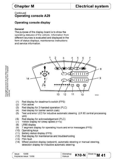
- Operating console display
General
Operating hours
Battery charge status
Wheel position display
Status symbols and maintenance symbols
Start-up test
Display of inductive automatic steering operating status
Error display
Travel and pump control system
- Connections
Control and logic section
Power section
- Pin assignment X1 1
- Block diagram peripheral travel and pump control system
- Description
- Travel setpoint
- Travel direction (forwards, reverse)
- Travel enable
- Travel programs
- Decelerations 1, 2 and 3
- Deceleration 1 (v = 0 km/h)
- Deceleration 2 (v = 2.5 km/h)
- Deceleration 3 (v = 1 km/h)
- Setpoint, hydraulic functions
- Operating hours counter on lowering
- Carbon brush monitoring
- Temperature monitor
- Status displays
ST-STAT
EIN-1
EIN-2
AUS-1
- Standard parameter set
- Battery type
- Setting operating hours
- Error memory
- Error list for error memory
- Description of errors
- Reading the setpoints out of the FPS
- Carbon brush monitor
- Summary of all the FPS addresses
- Summary of all travel parameters
Notebook (WIN95) - Preparation for programming the FPS
- Preparing the terminal program (TEWAK95) for reading out and programming parameters
Notebook (WIN95) - Programming the FPS
- Reading out parameters
- Programming parameters
- Guide to parameter settings for the terminal program (TEWAK95)
N Hydraulic system
Block diagram of hydraulic system
Hydraulics installation plan - Swivel shift fork
Hydraulics installation plan - Chassis
HMC-33 module
- Functional elements
- Adjustment work on the HMC-33 module
- Emergency relief valve
- Technical data
SWR module
DRH-CS2 module
Checking the hydraulic oil level
Oil filter
Removing the hydraulic unit
Hydraulic motor, technical data
Q Telescopic fork
Electrical adjustment of the telescopic fork
- General
- Electrical pre-adjustment
- Maximum extension depth
- Extension speed
- Ramp start
- Centre position stop
R Lubrication plan
Guide to oils/lubricants
Lubrication plan
Disposal of oil/lubricants
T Swivel shift fork
Plan of the guide, load-bearing and lateral guide rollers
Adjusting the tooth profile play
Adjusting the guide block
Mounting the shaft coupling
Straightening the swivel shift fork with the shaft coupling
Removing the shaft coupling
Adjusting the pulling cylinders
Removing the toothed shaft
Removing the swivel shift fork
Hydraulic motor OMP 160
V PLC
Commissioning a new PLC
Front panel of the PLC
Input/output assignments 1st binary I/O module
2nd binary I/O module
3rd binary I/O module
1st analogue I/O module
PLC error messages
Programming adapter
- Description
- Sketch of connections
Notebook (MSDOS) - "DIGSY" software
- Installing the "DIGSY" software
- Loading operating program files
- Starting the "DIGSY" software
- Copying an application program file
- Changing parameters in the PLC and programming
- Loading a new program in the PLC
- Current flow diagram
Examples for troubleshooting
- MW8 - List of error bits
Description of the error bits
Reading out the error bit bar
Table of PLC marker words
File Data
This file is sold by bg-store, an independent seller on Tradebit.
| File Size | 140 megabytes |
| File Type |