$14.95
Download NowSold by themanualexperts on Tradebit
The world's largest download marketplace
3,251,668 satisfied buyers
The world's largest download marketplace
3,251,668 satisfied buyers

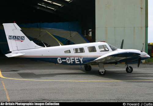
PIPER SENECA II SENECA SERVICE MANUAL PA-34-200T
INTRODUCTION
1-1. GENERAL. This manual contains service and maintenance instructions for the Piper PA-34-200T
Seneca II, designed and manufactured as a versatile airplane in the personal and business aviation field, by the Piper Aircraft Corporation, Vero Beach, Florida.
1-2. SCOPE OF MANUAL. Sections II and III comprise the service part of this manual; whereas, Sections IV through XIV comprise the maintenance instructions. The service instructions include ground handling,
servicing and inspection. The maintenance instructions for each system include troubleshooting, removal and installation of components, and corrective maintenance and testing; each major system of the airplane is covered in a separate section. Only qualified personnel should perform the operations described in this
manual. The description of the airplane included in this section is limited to general information. Section II gives leading particulars and principal dimensions, along with ground handling, while each major system is
described in its appropriate section of the manual For a more detailed description of the airplane, refer to the Owner's Handbook. 1-3. DESCRIPTION. The Seneca II is a six place (seventh seat optional), twin engine, low-wing monoplane
of all metal construction. The following paragraphs provide descriptions of the major components and systems. 1-4. WING. The laminar flow wing is of all metal stressed-skin, full cantilever, low-wing design, consisting
of two wing panels bolted to a spar box assembly in the fuselage. The wing tips are removable. The ailerons are cable and push rod controlled and are aero dynamically balanced. The trailing edge wing flaps are manually operated.
1-5. EMPENNAGE. The empennage consists of the fin, rudder, rudder trim tab, stabilator and stabilator
trim tabs. The rudder and stabilator are statically balanced.
1-6. FUSELAGE. The fuselage consists of three basic units: the nose section, the cabin section and the sheet-metal tail cone.1-7. LANDING GEAR. The tricycle landing gear is of the retractable air-oil strut type, consisting of a nose
wheel and two main wheels.
1-8. BRAKE SYSTEM. The standard brake system is operated hydraulically by dual toe brakes located on the rudder pedals or by a hand lever connected to a single brake cylinder below and behind the left center
of the instrument panel.
1-9. ENGINES AND PROPELLER. The airplane is powered by two Teledyne Continental six cylinder, direct drive, wet sump, horizontally opposed turbocharged engines. The left engine rotation is in the right-hand direction while the right engine rotates in the left-hand direction. The propellers are Hartzell full
feathering, constant speed units controlled by a governor mounted on each engine.
1-10. FUEL SYSTEM. The fuel system consists of two interconnected aluminum fuel tanks in each wing, having a combined capacity of 49 U.S. gallons, for a total capacity of 98 U.S. gallons. With optional fuel
tanks, each wing will have a combined capacity of 64 U.S. gallons, for a total capacity of 128 U.S. gallons.
Incorporated in the system are selector valves, gascolators, and electric priming fuel pumps and engine
driven pumps.
1-1 1. FLIGHT CONTROLS. The flight controls are conventional equipment, consisting of a control wheel
which operates the ailerons and stabilator, and pedals which operate the rudder. Duplicate controls are provided for the copilot. Trim controls are provided for the rudder and stabilator.
1-12. RADIO. Provisions are provided for the installations of microphone and headset jacks, loudspeaker, and panel space for radios and various avionic equipment.
1-13. CABIN HEATER, DEFROSTER AND FRESH AIR SYSTEM. Heated air for the cabin and defroster is obtained from the combustion heater located in the tail cone. Fresh air is supplied to the heater from an intake located in the dorsal fin. The combustion heater has a blower which is used to circulate heated or unheated air through six adjustable outlets. There is a defroster blower, in the same distribution system to provide additional defrost capability when required. There are six overhead fresh air vents supplied by a separate inlet in the dorsal fin. This system can be supplemented by an optional blower. 1-14. INSTRUMENT AND AUTOPILOT SYSTEM. Provisions for instrument installation include panels
for engine instruments and advanced instruments, as well as for an Autopilot system.
We are a Certified Disadvantaged Business Enterprise under FAA/DOT 49 CFR 26. All purchases from us are qualified for DBE goal credit. If your firm or business is required to meet a certain DBE, minority or small business goal, please let us know so that we can provide you with proof of our FAA DBE Certification. We are an expert in the Aviation Information Technology particularly dedicated in the preservation of technical manuals from motorcycles, automobiles to airplanes Manuals. I am an Eagle, an Embry Riddle Aeronautical University Alumni with strong aviation background and I love to ride motorcycle - my newest ride is a Kawasaki Ninja 650R. And yes of course I do like flying and even though I am unable to fly because this harsh economy I still plan on obtaining my Private Pilot License, right now I only have a limited number of flight hours.
While some manuals may appear similar for the same make and model of aircraft, each manual is unique and contains specific information about a particular aircraft, such as the equipment installed and weight and balance information. Manufacturers are required to include the serial number and registration on the title page to identify the aircraft to which the manual belongs. By purchasing this manual you agree to hold us harmless and indemnify us from any third party claims arising from the use of this manual. If you have insufficient experience or doubts your ability to do the work, all adjustments, maintenance, and repair should be carried out only by qualified mechanics. In order to perform the work efficiently and to avoid costly mistakes, read the text, thoroughly familiarize yourself with the procedures before starting work, and then do the work carefully in a clean area. Whenever special tools or equipment are specified, do not use makeshift tools or equipment. Precision measurements can only be made if the proper instruments are used, and the use of substitute tools may adversely affect safe operation.
File Data
This file is sold by themanualexperts, an independent seller on Tradebit.
| File Size | 29 megabytes |
| File Type | |
| Customer Rating |
Rated 5 out of 5, based on 1 review(s)
|