$27.99
Download NowSold by digitech on Tradebit
The world's largest download marketplace
3,252,005 satisfied buyers
The world's largest download marketplace
3,252,005 satisfied buyers

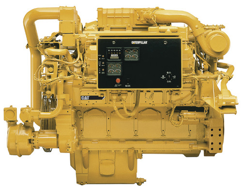
Caterpiller 3508 Diesel Engine Workshop Service & Repair Manual # 1 Top Rated Download
With this in-depth & highly detailed manual you will be able to work on your engine with the absolute best resources available, which will not only save you money in repair bills but will also help you to look after your investment, keeping your engine in pristine condition. With step by step instruction & highly detailed exploded pictures to show you how to complete the required job correctly & efficiently.
Below is an example of the topics this manual covers, an absolute wealth of information at your fingertips.
Model Covered:
Caterpiller 3508 Diesel Engines
Service Manual Covers:
Specifications for Engine Attachments,
3500 Industrial ............................................. 1
General Tightening Torque for Bolts, Nuts,
and Taperlock Studs.............................. 3
Torque for Flared and O-Ring Fittings4
Engine Design ........................................ 5
Fuel System
Fuel Injection ....................................... 8
Fuel Pressure Regulator (Earlier)........ 8
Fuel Pressure Regulator (Later).......... 9
Manual Shutoff Group ......................... 9
Fuel Injection Control Group ............... 10
Governor Fastener Group ................... 11
Governor Drive .................................... 11
Air Induction and Exhaust System
Camshafts ........................................... 12
Valves ............................................. 14
Valve Covers ....................................... 15
Valve Rocker Arms, Lifters and Bridges 15
Cylinder Heads.................................... 16
Turbocharger Impeller Installation....... 17
Turbochargers ..................................... 18
Exhaust Manifolds ............................... 22
Air Intake Shutoff................................. 23
Lubrication System
Oil Pump ............................................. 26
Oil Filter Bypass Valve (Earlier)........... 28
Oil Filter Bypass Valve (Later)............. 29
Oil Cooler Bypass and Cooling Jet
Sequence Valves................................. 30
Cooling System
Water Pump.............................................. 31
Aftercooler .............................................. 32
Water Connection Group - Outlet ............. 32
Water Temperature Regulators ................ 33
V-Belt Tension Chart................................. 33
Basic Engine Components
Cylinder Block ........................................... 34
Cylinder Liners .......................................... 35
Cylinder Liner Projection........................... 35
Pistons and Rings ..................................... 36
Connecting Rods ...................................... 37
Connecting Rod and Main Bearing Journals 38
Crankshaft .............................................. 39
Crankshaft Wear Sleeves and Seals ........ 40
Front Balancer Group (3508).................... 41
Lower Front Gear Group .......................... 42
Upper Front Gear Group (7N4871)........... 44
Rear Gear Group ...................................... 45
Flywheel .............................................. 47
Flywheel Runout ....................................... 48
Flywheel Housing...................................... 50
Flywheel Housing Bore............................. 52
Flywheel Housing Runout......................... 53
Alternators and Regulators .......................
Electrical System
Electric Starter Motors .............................
Starter Solenoids .....................................
Air Starter Motors ................................
Pressure Regulating Valve for
Air Starter Motor .............................................
Systems Operation, 3500 Industrial Engines 61
Engine Design ........................................ 63
Fuel System ............................................ 65
Fuel Injection Control Linkage............. 67
Fuel Injector......................................... 68
Woodward UG8 Lever Governors....... 71
Air Fuel Ratio Control .......................... 73
Air Inlet and Exhaust System................ 75
Aftercooler ........................................... 77
Turbochargers ..................................... 78
Valve System Components ................. 78
Lubrication System................................ 80
Cooling System ........................................ 82
Basic Block ............................................. 84
Cylinder Block, Liners and Heads ....... 84
Pistons, Rings and Connecting Rods.. 84
Crankshaft ........................................... 84
Camshafts ........................................... 85
Air Starting System................................ 86
Electrical System...................................... 88
Alternator............................................. 88
Starter Motor ....................................... 88
Starter Solenoid................................... 89
Circuit Breaker..................................... 89
Contactor Switch (Water Temperature) 90
Testing and Adjusting ........................... 91
Troubleshooting.............................................. 91
Fuel System .............................................. 107
Fuel System Inspection............................. 107
Checking Engine Cylinders Separately..... 107
Fuel Injector Testing ................................. 107
Injector Tester Preparation ....................... 108
Operation of the Tester ............................. 108
Leak Test for Injector Tester ..................... 109
Injector Test Sequence............................. 110
Fuel Pressure ........................................... 116
Engine Rotation ........................................ 117
Finding Top Center Position for No. 1
Piston .............................................. 117
Camshaft Timing....................................... 118
Startup Procedure..................................... 120
Crankshaft Positions for Fuel Timing........ 121
Fuel Timing .............................................. 122
Injector Synchronization............................ 123
Fuel Setting .............................................. 125
Fuel Setting Adjustment............................ 126
Engine Speed Measurement .................... 127
Woodward UG8 Lever Governor ................... 128
Compensating Adjustment........................ 128
Low and High Idle Speed Adjustment....... 129
Speed Droop Adjustment.......................... 129
Air Fuel Ratio Control..................................... 132
Air Inlet and Exhaust System.................... 133
Restriction of Air Inlet and Exhaust........... 133
Measurement of Pressure in Inlet Manifold 133
Exhaust Temperature............................... 134
Crankcase (Crankshaft Compartment)
Pressure ............................................. 134
Compression ............................................ 134
Cylinder Heads......................................... 134
Valves ............................................. 134
Bridge Adjustment.................................... 135
Crankshaft Positions for Valve
Clearance Setting .................................... 136
Valve Clearance....................................... 137
Lubrication System ........................................ 139
Too Much Oil Consumption...................... 139
Measuring Engine Oil Pressure................ 139
Oil Pressure is Low ................................. 140
Oil Pressure is High.................................. 140
Too Much Bearing Wear .......................... 140
Increased Oil Temperature ...................... 140
Cooling System ............................................. 141
Visual Inspection of the Cooling System.. 141
Testing the Cooling System ..................... 141
Test Tools for Cooling System ................. 141
Pressure Cap Test ................................... 142
Radiator and Cooling System Leak Tests 143
Water Temperature Gauge Test .............. 143
Water Temperature Regulator Test ......... 144
Basic Block ............................................. 145
Connecting Rod Bearings ........................ 145
Main Bearings .......................................... 145
Cylinder Block .......................................... 145
Projection of Cylinder Liners ..................... 145
Flywheel and Flywheel Housing................ 146
Checking Crankshaft Deflection (Bend).... 148
Vibration Damper ...................................... 149
Electrical System ............................................ 150
Test Tools for Electrical System ............... 150
Battery .............................................. 151
Charging System ...................................... 151
Starting System......................................... 152
Air Starting System ...................................
Caterpillar, 3161 Governor........................ 155
Governor Types ........................................ 157
Basic Governor ......................................... 159
Governor Components ............................. 159
Operation of the 3161 Governor ............... 161
Auxiliary Controls ........................................... 164
Manual Shutdown ..................................... 164
Pressure Shutdown................................... 164
Electric Shutdown .................................... 164
Manual Mechanical Speed Control........... 164
Pneumatic Speed Control......................... 165
Air Fuel Ratio Control................................ 167
Speed Adjusting Motor Governor Head.... 169
Manual Speed Setting Control.................. 169
Pneumatic Mid Speed Control .................. 170
Troubleshooting.............................................. 172
Governor Troubleshooting ........................ 172
Air Fuel Ratio Control Troubleshooting..... 176
Pneumatic Speed Setting
Control Troubleshooting........................... 178
Testing and Adjusting ................................... 180
Governor Oil Pump ................................. 180
Governor Preparation............................... 181
Governor Installation ................................ 182
Governor Adjustments ............................. 187
Auxiliary Controls ..................................... 192
Hydramechanical Protective System,
3500 Series Engines....................................... 197
Specifications
Shutoff Control Group .............................. 199
Thermostatic Pilot Valve .......................... 202
Accessory (Shutoff) Drive Group ............. 202
Air Intake Shutoff...................................... 206
Tachometer and Service Meter Drive ...... 209
Remote Shutoff Valve Group ................... 209
Electrical Switches ................................... 210
Systems Operation
Overspeed ............................................. 211
Low Engine Oil Pressure ......................... 211
High Coolant Temperature....................... 211
System Components................................ 211
System Hydraulics.................................... 214
Hydraulic Circuits (Earlier)........................ 214
Hydraulic Circuits (Later).......................... 228
Hydraulic Circuits, Later with an
Alarm System........................................... 232
Testing and Adjusting
Troubleshooting........................................ 239
Page
System Checks......................................... 243
System Tests ............................................ 245
Shutoff Speed Setting Adjustment............ 245
Wiring Diagrams ....................................... 247
3500 Industrial Engines.................................. 253
Disassembly and Assembly
Manual Shutoff ......................................... 257
Gauge Panel............................................. 259
Air Intake Shutoff ...................................... 262
Tachometer Drive ..................................... 269
Crankcase Breather.................................. 270
Water Temperature Regulators ................ 272
Water Pump.............................................. 275
Fuel Filter Housing.................................... 279
Fuel Priming Pump, Fuel Transfer Pump . 283
Oil Pump .............................................. 288
Oil Filter Housing ...................................... 293
Oil Pan .............................................. 300
Oil Sequence Valves................................. 304
Oil Cooler .............................................. 305
Turbochargers .......................................... 312
Exhaust Manifolds..................................... 321
Aftercooler .............................................. 322
Governor .............................................. 326
Governor Drive.......................................... 328
Hydramechanical Shutoff Control ............. 332
Hydramechanical Shutoff Drive ................ 345
Accessory Drive (Front) ............................ 347
Oil and Water Pump Drive ....................... 350
Crankshaft Vibration Damper................... 353
Crankshaft Front Seal and Wear Sleeve . 354
Crankshaft Rear Seal and Wear Sleeve .. 356
Front Drive Housing ................................. 358
Flywheel ............................................. 362
Flywheel Housing..................................... 363
Valve Covers............................................ 365
Rocker Shafts and Push Rods ................. 366
Fuel Injectors............................................ 369
Fuel Injection Control Linkage ................. 371
Cylinder Heads......................................... 377
Valves ............................................. 381
Bridge Dowels .......................................... 382
Connecting Rod Bearings ........................ 384
Front Balancer Group............................... 385
Rear Gear Group ..................................... 387
Spacer Plates........................................... 391
Crankshaft Main Bearings........................ 393
Pistons ............................................. 396
Cylinder Liners ......................................... 398
Camshafts ............................................. 400
Crankshaft ............................................. 407
Specifications for Engine Attachments
49Y1-UP, 95Y1-UP, 27Z1-UP, 65Z1-UP,
68Z1-UP, 71Z1-UP................................... 411
Ether Starting Aid................................... 416
Primary Fuel Filter.................................. 416
Fuel Filter Change Indicator Group...... 416
Governor ............................................. 417
Oil Pans .............................................. 421
Oil Filter Bypass Valve ........................... 422
Duplex Oil Filter ..................................... 423
Oil Scavenge Pump ................................ 424
Exhaust Manifolds .................................. 426
Turbochargers......................................... 427
Air Intake Shutoff .................................... 436
Front Gear Groups.................................. 437
Auxiliary Drive ........................................ 440
Tachometer Drive ................................... 441
Trunnion (Front)...................................... 443
Engine Front Support Group (Wide) ..... 443
Vibration Damper Group ........................ 444
Front Mounting Group............................ 447
Stub Shafts .............................................. 447
Time Delay Relay .................................... 449
Heaters, Jacket Water ............................ 449
Magnetic Pickup ..................................... 449
Tachometer, Digital ............................... 450
Contactors .............................................. 451
Pressure Switches ................................. 452
Temperature Switches .......................... 453
Sending Units, Oil Pressure .................. 454
Tachometer, Electric .............................. 454
Gauges, Ammeter/Oil Pressure/
Water Temperature ................................ 455
Air Shutoff Solenoids ............................. 456
Air Compressor Group .......................... 457
Air Control Valve Group ........................ 458
Electric Protective System for Engines
Equipped with Reversal Protection .............. 459
Components ........................................... 460
Individual Circuit Description .............. 462
Engine Stopped...................................... 462
Starting Engine.......................................
Engine Starts to Run: No Faults ...........
Engine Runs at Rated Speed:
No Faults .............................................
Pressure (At Engine Speeds above Oil Step
Speed Setting) ........................................
Engine Shutdown Due to Fault:
Loss of Engine Oil..................................
Engine Running Below Oil Step
Speed Setting: No Faults (or Just
Accelerating through Step Speed) .......
Engine Shutdown Due to Fault: Low Oil
Pressure (At Engine Speeds Below Oil
Step Speed Setting) ...............................
Engine Shutdown Due to Fault:
Coolant Overheating..............................
Engine Shutdown Due to Fault:
Engine Overspeed..................................
Engine Shutdown Due to Fault:
Engine Reversal ....................................
Shutdown System with 2301 Electric
Governor Control: No Faults.................
Troubleshooting..................................... 484
Functional Test ....................................... 485
System Problem Index........................... 486
System Troubleshooting Charts,
Preliminary Checks................................ 487
Overspeed, Chart A........................... 488
Crank Terminate, Chart B ................. 490
Step Oil Pressure, Chart C ....................... 492
Reversal Detection, Chart D .................... 494
Troubleshooting Procedures ........................ 496
Overspeed Setting Calibration,
Procedure A .............................................. 496
Crank Terminate, Speed Adjustment,
Procedure B .............................................. 497
Oil Step Calibration, Procedure C............. 498
Overspeed Verify Test, Procedure D........ 499
Reversal Detection, Procedure E.............. 500
Sensor Assembly Verify, Procedure F...... 501
On/Off Time Delay (Relay), Procedure G . 503
Wiring Diagrams.............................................. 504
Electric Protective System Schematic ..... 505
Engine Wiring Diagram............................. 506
Typical Junction Box Wiring Diagram ....... 507
Customer Wiring with Electric
Protective System .................................... 510
Electrical Protective System for Generator Set,
Industrial and Marine Engines............... 513
Components............................................ 514
Individual Circuit Description................ 516
Engine Stopped....................................... 516
Starting Engine ...................................... 518
Engine Starts to Run: No Faults ........... 520
Engine Runs at Rated Speed: No Faults 522
Engine Shutdown Due to Fault:
Loss of Engine Oil Pressure (At Engine
Speeds Above Oil Step Speed Setting) 524
Engine Shutdown Due to Fault: Low Oil
Pressure (At Engine Speeds Below Oil
Step Speed Setting)................................ 528
Engine Shutdown Due to Fault:
Coolant Overheating ...................................... 530
Engine Shutdown Due to Fault:
Engine Overspeed.......................................... 532
Shutdown System with 2301 Electric
Governor Control: No Faults......................... 534
Electric Protective System
Functional Tests............................................. 536
Speed Specification Chart ............................ 537
Troubleshooting ............................................ 538
Problem Identification Index ......................... 539
System Troubleshooting Charts,
Preliminary Checks ........................................ 540
System Arming, Chart A........................... 541
Overspeed, Chart B.................................. 542
Crank Terminate, Chart C ........................ 544
Step Oil Pressure, Chart D....................... 546
Troubleshooting Procedures
Overspeed Setting Calibration,
Procedure A ............................................. 548
Crank Terminate Speed Adjustment,
Procedure B ............................................ 549
Oil Step Calibration, Procedure C ............ 550
Overspeed Verify Test, Procedure D ....... 551
Magnetic Pickup Verify, Procedure E....... 552
On/Off Delay (Relay), Procedure F .......... 553
Wiring Diagrams............................................. 554
Electric Protective System Schematic...... 555
Engine Wiring Diagram ............................ 556
Typical Junction Box Wiring Diagram ...... 557
Customer Wiring with Electric
Protective System ................................... 560
Operation and Maintenance, 3508 Industrial Engine
Safety .............................................. 565
Operation Section................................... 568
Model Views.............................................. 569
Gauges .............................................. 571
Shutoff and Alarm System Components... 573
Engine Controls ........................................ 575
Before Starting the Engine ....................... 578
Starting the Engine ................................... 579
After Starting the Engine........................... 582
Stopping the Engine.................................. 583
After Stopping the Engine ......................... 584
Lifting Engine and Attachment.................. 584
Engine Storage ........................................ 585
Maintenance Section ...................................... 586
Serial Number Location ............................ 587
Maintenance Recommendations .............. 587
Fuel, Coolant and Lubricant
Specifications ......................................... 590
Refill Capacities ........................................ 592
Engine Specifications................................ 592
Recommended Lubricant Viscosities........ 593
Lubrication and Maintenance Chart ......... 594
When Required......................................... 596
Every 10 Service Hours or Daily............... 597
Every 50 Service Hours or Weekly .......... 609
Every 100 Service Hours or 2 Weeks....... 611
Every 250 Service Hours or Monthly......... 612
Every 500 Service Hours or 3 Months ...... 617
Every 1000 Service Hours or 6 Months .... 618
Every 2000 Service Hours or 1 Year......... 624
Troubleshooting Section ....................... 628
This manual is very easy to use, it is designed in PDF format to simply view on your windows pc or mac/tablet/smartphone etc. You can print what you need when you need it and throw away when the work is complete. You can also print this entire manual if you would like to have a hardcopy.
The ONLY Workshop Service Manual You Will Ever Need.
Instant Download means there is NO shipping costs or waiting for a CD or paper manual to arrive in the mail! You will receive this manual within minutes of placing your order via Instant Download on completion of payment via our safe & secure payment processor. We accept ALL major credit/debit cards/PayPal.
Smart, Convenient, Fast! - Download Today!
If you are looking for a specific manual & cant find it then either search our shop http://digitech.tradebit.com (link also above) or contact our customer support team via the Contact Seller link with details of the required manual & we will do our absolute best to find it for you as we have one of the biggest manual databases online.
Thanks For Visiting Our Page & Have A Nice Day!
Tags:
caterpiller, cat, 3508, diesel engine, service, workshop, repair, shop, wsm, fsm, pdf, download, manual, specifications, lube points, oil types, periodic maintenance and tune-up procedures, engine servicing, disassembly, reassembly, engine removal, fuel and lubrication systems, carb rebuild, carb adjustments, electrical system, ignition, charging, starter, battery, switches, chassis, wheels, brakes, steering, suspension, axles, chassis assembly, servicing information, wiring diagrams, wire/cable/hose routing, tools, tightening torques, service data, complete engine service, fuel system service, all factory repair procedures, gearbox, exhaust system, suspension, fault finding, clutch removal and installation, front suspension, bodywork, gearbox service, gearbox removal and installation, cooling system, detailed specifications, transmission, factory maintenance schedules, electrics, engine firing order, brake servicing procedures, u-joint service procedures, cv joint service procedures, timing chain service, exhaust service,
File Data
This file is sold by digitech, an independent seller on Tradebit.
| File Size | 48 megabytes |
| File Type |