$14.95
Download NowSold by belgreen on Tradebit
The world's largest download marketplace
3,253,479 satisfied buyers
The world's largest download marketplace
3,253,479 satisfied buyers

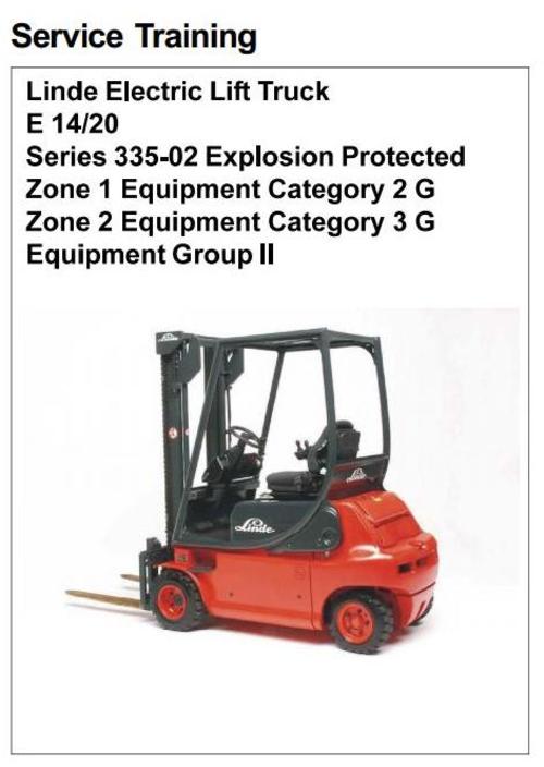
Linde Electric Lift Truck Series 335-02 Explosion Protected: E14, E16, E16C, E18C, E16P, E18P, E20P Service Training Manual
Covered models
E14-02 EX
E16-02 EX
E16C-02 EX
E18C-02 EX
E16P-02 EX
E18P-02 EX
E20P-02 EX
Format: PDF, 126 pages
Language: English
Table of contents:
General information
Instructions
Explosion protection measures at the truck
Traction motors
Pump motor
Battery
Safety measures
Marking
Commissioning
Installation and replacement of batteries
Operation and charging
Maintenance, repair
Environmental conditions
Battery plug-in unit
Design of battery connector
Design of battery coupling
Dismantling of Battery plug-in unit to line connection
Dismantling of battery coupling
Installation of battery coupling
Dismantling the battery connector
Mounting the battery connector
Wheels
Fork arms
Brake
Indicator instruments
Electrical system
Tightening torques for covers of flameproof enclosures
Special tools
1 Drive - traction motor
1.1 Traction motor
1.1.1 Technical data
1.1.2 General
1.1.3 Checking the carbon brush wear of the traction motors, replacing the carbon brushes
1.1.4 Cleaning of the traction motors
2 Drive - transmission
2.1 Removing and installing the drive axle
2.1.1 Removing the driving axle and cleaning the traction motors
3 Truck Construction
3.1 Driver seat
3.1.1 Replacement of seat switch
3.1.2 Checking the leakage resistance of the driver seat
4 Steering system and wheels
4.1 Servostat
4.1.1 Removing and installing the reed Contact
4.1.2 Curve sensor
4.1.3 Wheels and tyres
4.1.4 Checking the leakage resistance of the driving wheels
5 Operator's control elements
5.1 Truck speed controller
5.2 Joysticks
5.2.1 Replacement of joysticks
5.3 Brake actuation
5.3.1 Replacement of brake pads
5.3.2 Replacement of temperature switches 1B8/1B9
6 Electric system
6.1 Flameproof enclosures
6.1.1 Maintenance of flameproof enclosures
6.1.2 Control housing
6.1.3 Flameproof enclosure - intrinsic safety
6.1.4 Flameproof enclosure For voltage transformer - lighting
6.1.5 Checking the PG-glands for their sealing effect
6.1.6 Checking the condition and firm seat of electric lines
6.2 Checking the insulation resistance of the electric system
6.2.1 Procedure / determination of limit values for insulation monitoring in potentially explosive atmospheres
6.2.1.1 General information
6.2.2 Manual checking of insulation resistance of the electric system
6.3 Intrinsically safe circuits
6.4 Switch amplifier - function and description (Design in accordance with 94/9EC)
6.4.1 Basic circuit diagram of a switch amplifier
6.4.2 Performance test of the switch amplifiers
6.4.3 Replacement of switch amplifiers
6.5 Zener barrier, Function and description (designed in accordance with 94/9EC)
6.5.1 Terminal markings of Zener barrier
6.5.2 Basic circuit diagram of Zener barrier
6.5.3 Checking the internal resistances of the Zener barriers
6.6 Voltage supply
6.7 Monitoring unit 1V1 and Enable signal
6.8 Insulation monitoring (94/9/EC category 2G - zone 1)
6.8.1 Checking the insulation monitoring system 3V3
6.8.2 Circuit diagram for insulation monitoring system
6.9 Terminal assignment X1
6.9.1 Terminal strip XZ1 converter housing - lighting
6.10 Circuit diagram
6.10.1 Traction control
6.10.2 Voltage transformer, Thermal protection, composite instrument
6.10.3 Lift control
6.10.4 Traction control and insulation monitoring
6.10.5 Lighting and aux. electric system
6.11 Schematic drawing of individual components in the flameproof enclosures - Zone 1
6.11.1 Control housing - (top view)
7 Working hydraulics
7.1 General information
7.2 Maintenance and emergency functions of working hydraulics
7.2.1 Manual tilting of the mast
7.2.2 Lowering the fork carrier manually, category 2 G (zone 1)
7.2.3 Lowering the fork carrier manually, category 3G (zone 2)
7.2.4 Removal and installation of Hydraulic control valve (zone 1)
7.2.5 Replacement of carbon brushes
File Data
This file is sold by belgreen, an independent seller on Tradebit.
| File Size | 29 megabytes |
| File Type |