$23.00
Download NowSold by belgreen on Tradebit
The world's largest download marketplace
3,251,313 satisfied buyers
The world's largest download marketplace
3,251,313 satisfied buyers

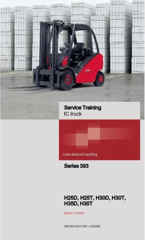
Linde Forklift Truck 393 Series: H25, H30, H35 Service Training manual and Schematic Diagrams
Original factory manuals for Linde Forklift Trucks, contains high quality images, circuit diagrams and instructions to help you to operate and repair your truck
Covered Models:
H25D
H30D
H35D
H25T
H30T
H35T
Format: ZIP, included files:
Service Training Manual: PDF, 528 pages
Circuit Diagrams LPG Truck, PDF, 209 pages
Circuit Diagrams Diesel Truck, PDF, 180 pages
LTC Unit Replacement Manual, PDF, 126 pages
Language: English
Table of contents:
0. Product information
Foreword
The truck
Truck operation when using a shovel
Diagnostics
LTC basic structure
1. Engine
LPG engine
Description of the drive
Technical data for VWBEF ....
Engine block
Ribbed V-belt - removal and fitting
Toothed belt- removal and fitting, tensioning
Cylinder head - removal and fitting
Compression - check
Checking hydraulic bucket tappets
Cooling
Coolant -draining and filling
Coolant thermostat- removal and installation
Water pump - removal and installation
Coolant pump - Checking for wear
Engine electrics
Three-phase alternator
Electronic ignition system up to 08/2005, overview
Electronic ignition control unit
Electronic ignition system from 09/2005, overview
Shut-down due to lack of gas
LPG system
Safety guidelines for LPG (extract)
Basic rules when working with LPG
Sealing plastic pipe unions
Functions
LPG system -functions
Shut-down due to lack of gas
Evaporator -functions
Mixer -functions
Default settings for the mixer
Revolution control (from 12/2007)
LPG shut-off valve
LPG system with lambda control system
Exhaust gases -composition
Lambda control system
Checking and adjusting the mixer
Locations - overview
Leakage test on LPG system
LPGtank
Level display with single replacement cylinders(special equipment)
Removing and installing the level display and 80 filling stop valve
The following safety measures must be observed
Carrying out assembly operations
Bleeding the LPG tank
The following safety measures must be observed
Procedure for bleeding
BEU diesel engine
Description of the drive
BEU technical data
Particularities of the 1.9-litre engine
The electronic engine control unit
Sensors
Coolant temperature sending unit 0B1
Engine speed sensor 0B2
Actual speed sensor 1B1
Fuel temperature sending unit 0B3
Sensor 0B4
Needle stroke sensor 0B5
Height sensor
0B3 control gate valve travel sensor
Glow plug system
Pre-heater system
Glow plugs - engine 0R1
Fuel supply
Fuel metering
Fuel quantity actuator 0B3
Fuel shut-offvalve 0Y1
Injection timing device- replacement of O-ring on cover
Start of injectionvalve 0Y2
Start of injection -governing
Start of injection - dynamic check and adjustment
Injection nozzle -Two-spring nozzle holder
Injection nozzles - removal and installation
One-way restrictor
Injection system - overview
Injection system -supply voltage check
Injection pump - removal and refitting, Exchanging the toothed belt
Injection pump - removal and installation
Injection pump - pump and toothed belt adjustment
Engine block
Ribbed V-belt- removal and fitting
Crankshaft oil seal on pulley end - removal and installation
Crankshaft sealing flange - removal and installation
Checking the cylinder head
Cylinder head - removal and fitting
Cylinder head - compression check
Valve gear
Oil pressure and oil pressure switch - check
Oil sump
- removal and installation
Checking hydraulic bucket tappets
Camshaft- removal and installation
Vacuum pump
Air volumeter 0B6
Solenoid valve for charge pressure limitation 0Y4
Turbocharging system exhaust turbocharger
Exhaust gas recirculation - removal and installation
Exhaust gas recirculation -check
Cooling
Coolant- draining and filling
Coolant thermostat- removal and installation
Water pump - removal and installation
Coolant pump - Checking for wear
Engine electrics
Three-phase alternator
Replacing the engine control unit /immobilizer
Self-diagnostics
Self-test- introduction
Self-diagnostics -troubleshooting
Standardised measured value blocks
Measured value block 01 -evaluation
Measured value block 03 -evaluation
Measured value block 04 -evaluation
Measured value block 05 -evaluation
Measured value block 07 -evaluation
Measured value block 10 -evaluation
Measured value block 11 -evaluation
Measured value block 12 -evaluation
Measured value block 13 -evaluation
CBHAdiesel engine (pump injection)
Description of the drive
CBHA technical data
Sensors
Checking the coolant temperature sensor 0B1
Checking the engine speed sensor 0B2
Removing and installing the engine speed sensor 0B2
Actual speed sensor 1B1
Checking the hall-effect sensor 0B8
Checking the fuel temperature sensor 0B3
Checking suction pipe temperature sensor 0B4
Checking the suction pipe pressure sensor 0B4
Glow plug system
Ceramic glow plugs 0R4
Fuel supply
Rules for working on the direct fuel injection system
Checking the tandem pump delivery pressure
Removing and installing the tandem pump
Pump injection unit- overview
Pump injection unit- Checking valves 0Y2
Removing and installing the pump injection unit
Changing the O-rings and thermal protection seal on the pump injection unit
Engine block
Cylinder block -overview
V-ribbed belt- removal and fitting
Removing and installing the free-wheel belt pulley
Toothed belt -removal and fitting, tensioning
Changing the crankshaft sealing ring on the toothed belt pulley side
Removing and installing the crankshaft sealing flange
Cylinder head -overview
Cylinder head cover- removal and installation
Removing and installing the cylinder head
Cylinder head -checking the compression pressure
Valve train - overview
Valve stem covers - removal and installation
Valves
Checking the camshaft for axial play
Removing and installing the camshaft sealing ring
Removing and installing the camshaft
Oil filter and oil cooler -overview
Removing and installing the oil sump
Suction pipe -overview
Checking the suction pipe flap switchover
Checking the switch valve for suction pipe flap 0Y11
Vacuum hoses -connection diagram
Air volumeter 0B6
Checking the charge pressure limitation solenoid valve 0Y4
Exhaust gas recirculation
Exhaust gas recirculation - overview
Checking exhaust gas recirculation
Checking the exhaust gas recirculation valve 0Y3
Checking the mechanical exhaust gas recirculation valve
Cooling
Checking the cooling system for leaks
Draining and filling coolant
Removing and installing the coolant thermostat
Removing and installing the coolant pump
Self-diagnostics
Self-diagnostics - introduction
Error code table
Standardised measured value blocks
Measured value block 01 -fuel injection quantity
Measured value block 03 -exhaust gas recirculation
Measured value block 04 - pump/nozzle unit activation
Measured value block 07 -temperatures
Measured value block 10 -air variables
Measured value block 11 -charge pressure control
Measured value block 12 - heating status
Measured value block 13 - idling smooth running control
Measured value block 18 -valve status of pump injection units
Measured value block 23 - BIP deviation (solenoid valve switching times)
2. Drive axle
Description
Technical data about traction drive
System overview
Drive unit
Hydraulic remote control with electronic activation- old version
Hydraulic remote control with electronic activation- Version with round solenoids
Auxiliary brake valve up to 09/2006
Auxiliary brake valve from 1 0/2006
Start of delivery of the pump
Removing and installing the HPV variable displacement pump coupling flange .
Bypass valve
Output unit
Hydraulic fan drive
Hydraulic truck diagnostics
Overview and explanations about diagnostics
HPV 75 -02 pressures -tests
Hydrostatic travel drive - check
Wheel motor HMF 550 R-disassembly
Wheel motor HMF 550 R-checking the bearing, seals
Wheel motor HMF 550 R-sealing after inspection
Wheel motor HMF 550 R - exchanging the bearing
3. Chassis, bodywork and fittings
Chassis
Axle suspension
Instructions for working with gas springs
Driver's seat
Driver's seat controls
Service instructions
4. Steering, brake and wheels
Steering system
Steering system - functional description
Brake system
Brake release valve
Brake cables - adjustment
Checking the brake system
6. Electrics / Electronics
General
Safety instructions for electrical equipment
EMC- Electromagnetic compatibility
Electrostatic charging
CAN bus
Central electrical system
Linde Truck Control (LTC)
Arrangement of the interface connectors console -truck
Layout of relays and fuses for standard and optional equipment
Indicator unit
Checks
Testing the LTC (vehicle and lift controller)
Testing the VW controller and immobiliser(WFS)
Checking wiring harness
Testing sensors
Testing the indicator unit
7. Hydraulic system
Working hydraulics
Functional description of the control valve
Overview
Operating hydraulics circuit diagram
Function characteristics
Pressure relief valve
DepressurisationAuxiliary hydraulics 1and 2
Hose layout pump - control valve
Hose layout control pressure supply
Cleaning work on the Linde control valve
8. Load lift system
Lift mast
Lift mast - identification
Mast - removal and installation (all series)
Installation of mast type 188
A dusting the lift chain (all series)
Setting the roller play
Roller clearance - fork carrier in the inner mast, type 1 88
Roller play - centre mast, inner mast profile, family 1 88
Roller play - outer mast profile, family 1 88
Removal of slide pads - standard mast
Removal of slide pads - duplex mast
Removal of slide pads -triplex mast
Lift cylinder (outer) - removal and installation
Lift cylinder (centre) - removal and installation
Lift cylinder - sealing
Setting the tilt angle sensor
Tilt cylinders
Hose reservoir- removal, exchanging hose, sealing, fitting
Annex
10 Circuit diagrams
Hydraulic circuit diagrams
Hydraulic circuit diagram up to 09/2006
Traction, working and steering hydraulics
Wiring diagrams up to 08/2005
Wiring diagram (basic equipment for LPG engine), page 1
Circuit Diagram Standard Equipment LPG Engine, Sh. 2
Circuit Diagram Standard Equipment, LPG Engine, sheet 3
Wiring diagrams (LPG)
LPG basic equipment sheet 1
Basic equipment for LPG sheet 2
Basic equipment for LPG sheet 3
Wiring diagrams (diesel)
Basic equipment for diesel sheet 1
Basic equipment for diesel sheet 2
Basic equipment for diesel sheet 3
Basic equipment for diesel with pump injection engine- sheet 1
Basic equipment for diesel with pump injection engine -sheet 2
Basic equipment for diesel with pump injectionengine - sheet 3
Special equipment wiring diagrams
Special equipment sheet 1 working headlights, lighting, direction indicator system, brake light, interior lighting
Special equipment sheet 2 -Windscreen wiper, seat heater, radio
Special equipment sheet 3 - Heater, air conditioning, rotating beacon, reversing signal
Special equipment sheet 4 - Hazard warning system for reversing, higher lighting
Special equipment sheet 5 - Lift mast positioning, hydraulic oil microfilter indicator, vehicle deactivation, Forklift Data Management
Special equipment sheet 6 - Particulate filter, diesel filter water trap warning
Special equipment sheet 7 - LPG volume display, 12V socket, working headlights pos. 5 and 6, coolant and engine oil level monitoring
Special equipment sheet 8 - Battery main switch with indicator unit voltage supply, exchangeable particulate filter, rear window heater, camera system
UPAsheet7: speed limitation, switchable, switch-off delay
File Data
This file is sold by belgreen, an independent seller on Tradebit.
| File Size | 239 megabytes |
| File Type | ZIP |
| Customer Rating |
Rated 5 out of 5, based on 1 review(s)
|