$19.00
Download NowSold by belgreen on Tradebit
The world's largest download marketplace
3,255,750 satisfied buyers
The world's largest download marketplace
3,255,750 satisfied buyers

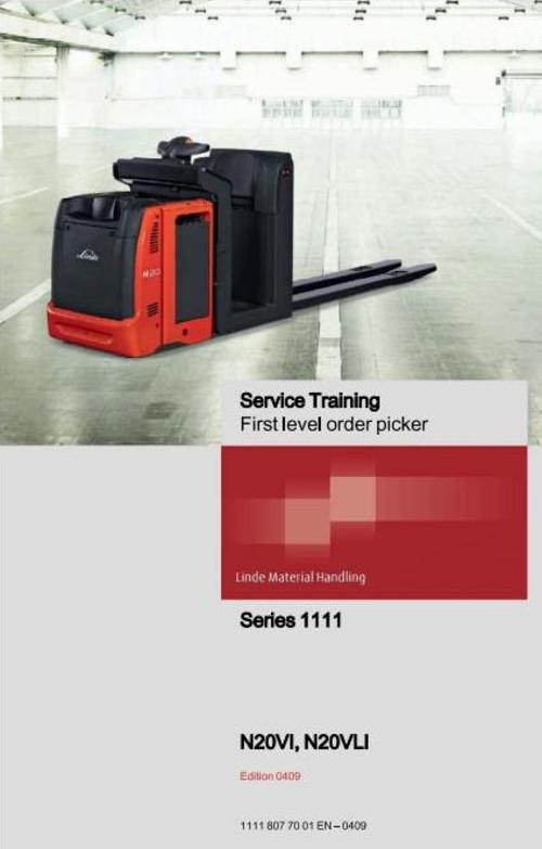
Linde Order Picker Type 1111: N20VI, N20VLI Service Training (Workshop) Manual
Original factory manuals for Linde Forklift Trucks, contains high quality images, circuit diagrams and instructions to help you to operate and repair your truck
Covered models:
N20VI
N20VLI
Format: PDF, 196 Pages
Language: English
Contents:
0. Product information
Description
Order picker N20VI-VLI type 1111
Diagnostics
Accessing truckinformation
Can Bus Network
Multi-function indicator, breakdown code display
Breakdown code descriptions
TRACTION fault codes
LIFT fault codes
Fault codes -STEERING -Main Controller
Fault codes -STEERING -Safety Controller
1. Engine
Traction motor
Description
Removing the drive motor
Traction motor bearing
2. Drive - Transmission
Drive unit
Description of the drive unit
Removal/replacement of the drive unit
Fitting the drive unit to the chassis
Reducer
Gear reducer
Reducer unit
Removal / refitting reducer gearbox
3. Truck structure
Driver's platform
Description
Removing the dashboard
Removing the platform backrest
Mounting the driver's platform
4. Steering, braking and wheels
Electrical steering
General
Control handlebar
Removing the handlebar
Steering centre (LORD)
Steering geared motor
Removal/replacement of the steering motoreducer
Wheel position potentiometer (3B3)
Steering motor (3M1)
Electric steering adjustment
Brake
Hydraulically assisted electromagnetic parking brake
Wheels
Rolling base
Drivewheel
Suspended stabiliser wheel
Support rollers
6. Electrical equipment
N20VI/N20VLI type 1111
General
Location of platform connectors and controls
Operation of the N20 VI and N20 VLI type 1111 order pickers
Electrical panel
Manipulating the electrical plate
Fuse access
Traction (L.A.C. 03)
Tractidhydrauliccontroller-LAC03/1A1
Functions of the "Inputs/ Outputs" of the LAC 03
Turning on the LAC Controller- 1A1
Replacing the L.A.C. box (1 A1)
Setting up the control module (1A1)
Accelerator (1S21, 1 S22) and potentiometer (1B1) controls
Horn4H1
Hydraulically assisted electromagnetic brake Y1
Traction motor speed sensor 1 B2
Monitoring traction motor temperature 1B6
Battery locking sensor 1S1 9
Controlling the LAC cooling fan 9M1
Speed restriction n°1 and n°2 (options)
Hydraulic controls
Controlling platform detectors 2B6, 2B7 and 2B9
Controlling Initial Lift detectorsl B3 and 1 B4
Controlling mast detectors (N20 VLI)2B1 and 2B6
Platform height detectors 2B7.2B8 and 2B9
Initial Lift height detector 1 B4 and 1 B3
Fork height detectors 2B1 and 2B6(N20VLI)
Hydraulics functions
Mast hydraulic pressure
Initial Lift operation
Electrical steering (L.E.S. 40
Electric steering controller L.E.S./3A1
Functions of the "Inputs/ Outputs," LES(3A1)
Replacing the L.E.S. box (3A1)
Setting steering control module parameters (3A1 )
LES Controller power up
Speed reduction when turning (with LAC n°390 360 85 19)
Multifunction display (Bauser)
4-button multifunction indicator (version CAN BUS)
Programming the multifunction indicator
Changing the multifunction display
Replacing the key (S1) with a DIGICODE
7. Hydraulic assembly
Hydraulic equipment
N20VI and N20VLI configurations
Description of the pump unit
N20 VI & N20 VLI: installation and tightening torques of pump unit components
Platform / mast selection block (N20 VLI)
Replacing the motor pump brushes
Working on the pump unit
8. Lifting system
Initial Lift
Fork carriage
Annex
10. Diagrams
Circuit diagrams
Power
N20 VI controls
N20VLI controls
Hydraulic diagrams
N20 VI type 1111
N20VLI type 1111
File Data
This file is sold by belgreen, an independent seller on Tradebit.
| File Size | 47 megabytes |
| File Type |