$29.00
Download NowSold by belgreen on Tradebit
The world's largest download marketplace
3,252,177 satisfied buyers
The world's largest download marketplace
3,252,177 satisfied buyers

Jungheinrich Electric Lift Truck EFG-DF/DC Series: 213-220 dc, 216k dc, 218k dc DF 13-DF 20, DF 16L, DF 18L Workshop Manual
Original factory manuals for Jungheinrich Forklift Trucks, contains high quality images, circuit diagrams and instructions to help you to operate and repair your truck. All Manuals Printable and contains Searchable Text
Covered models:
213 dc (01.2004-08.2004)
215 dc (01.2004-08.2004)
216 dc (01.2004-08.2004)
216K dc (01.2004-08.2004)
218 dc (01.2004-08.2004)
218K dc (01.2004-08.2004)
220 dc (01.2004-08.2004)
DF 13 (07.1998-12.2003)
DF 15 (07.1998-12.2003)
DF 16 (07.1998-12.2003)
DF 16L (07.1998-12.2003)
DF 18 (07.1998-12.2003)
DF 18L (07.1998-12.2003)
DF 20 (07.1998-12.2003)
Format: PDF, 292 Pages
Language: English
Contents:
2 Technical Description of Components
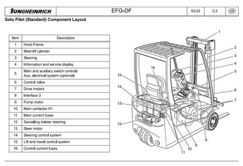
Solo Pilot (Standard) Component Layout
Multi Pilot (Option) Component Layout
Chassis / Assembly
Drive System
Drive system assembly
Assembly: Drive motor
Assembly: Transmission System
Wheels / Axles
Drive Switch / Drive Pedal
Brake System
Brake pedal:
Parking brake:
Multi- plate brake:
Steering system
Steering column:
Swivelling bolster:
Steering System Block Diagram
Chassis / Load Section Connection
Tilt cylinder:
Hydraulic System
Control Panel
Control valve:
Pump Motor / Pump / Pressure Filter
Electrical System
Solo Pilot Block Diagram
Multi Pilot Block Diagram
3 General Truck Data, Test and Setting Valves
General Truck Data
Test and Setting Values
Torques
4 Truck - Maintenance
5 Service Manual Items
Replacement/ adjustment steering angle potentiometer B 600
Speed reduction setting instructions B 6006
Replacing the Brake Multi- Plates D 6001
Stopping distances, minimum braking D 6360. 03
Main brake cylinder (single stage) D 6360. 14
Instructions for the installation of bra- ke tubes D 6360. 16
Tightening torques for screwed con- nections on brake sys
Changing of the brake fluid D 6360. 19
Parking brakes D 6360. 21
Steering auxiliary motor connection layout F 4001
Test dimensions and adjustments toi hoist frames incorporating oblique suf
Length check of load chains G 6355. 01
Fork tines G1 6401 .01
Pilot Valve Basic Setting I 5001
Pilot Valve Basic Setting I 5007
Mounting instructions for cutting ring joints I 6600. 06
Lowering brakes and line break safety devices 1 6632.01
ELSE-CHECK J 5002
Instructions for the prevention of ac- ciderits and damage to equipment whi
Notes on how to avoid acciderits and material damage when carrying out tr
Code list - cable colours 3 6900.08
6 MP1514F/ H CAN Bus Control System (2 motor drive)
Control System - Operational Description
Removing the contactor rack MP1514F
Drive Current Control Systems - Operational Description
LED on the MP1514F
MP1514F / MP1514F2 Electrical Plug Layout
MP1514H
Lifting Control System Operational Description on the MP1514H
Electrical Plug Layout
Removing the Interface Card
Removing the Masterpilot
Interface 3
Operational Description
LED on Interface 3
Electrical Plug Layout
Interface 4
Operational Description
LED on Interface 4
Electrical Plug Layout
Masterpilot (optional)
Operational Description
Masterpilot Electrical Plug Layout
Block Diagram for EFG- DF
with Manual Valve Lever
with Masterpilot
LISA User Mode Layout
LISA Service Mode Layout
Tract Parameter Setting
Horn Function Table
Parking Brake Function Table
Option 1 Table
Tabelle Option 2
Lifting Parameter Setting
Side Shift Function Table
Hydraulic function locking - Masterpilot Trucks
Steering Parameter Setting
Truck Length Table
Battery Parameter Setting
Battery Setting Table
Error Logbook Schematic
Diagnostics -
Travel
- Lifting
- Steering
Commissioning a Truck with the CAN- LISA System
Truck Setting
Setting Standard Parameters
Setting Key Parameters
Adjusting Potentiometer Values
the steering angle potentiometer
the lift potentiometer
7 Electrical Wiring Diagrams
Terminology Listing
MF Circuit Diagram (Multi-Pilot )
HS Circuit Diagram (Solo-Pilot )
Circuit Diagram EFG 213-220 dc SP
MF (Multi-Pilot) Wiring Diagram
HS (Solo-Pilot) Wiring Diagram
Wiring diagram (Solo-Pilot)
Wiring diagram (Multi-Pilot)
Wiring diagram EFG 213-220 dc SP
EFG 213-220 dc MP wiring diagram
EFG 213-220 dc MP wiring diagram
Optional:
Roadtraffic regulations lighting
Back-up light/ Buzzer Reversing dir
MSG 75 driver's seat
MSG 65 driver's seat with heating
SG 20 driver's seat
MSG 20 driver's seat with heating
Savas driver's seat
8 Hydraulic Wiring Diagrams
File Data
This file is sold by belgreen, an independent seller on Tradebit.
| File Size | 57 megabytes |
| File Type |