$29.00
Download NowSold by belgreen on Tradebit
The world's largest download marketplace
3,252,177 satisfied buyers
The world's largest download marketplace
3,252,177 satisfied buyers

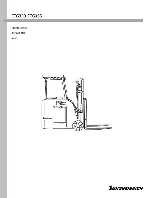
Jungheinrich Electric Lift Truck ETG-Series: ETG350, ETG355 (from 01.2010) Workshop Manual
Original factory manuals for Jungheinrich Forklift Trucks, contains high quality images, circuit diagrams and instructions to help you to operate and repair your truck. All Manuals Printable and contains Searchable Text
Covered models:
ETG350 (from 01.2010)
ETG355 (from 01.2010)
Format: PDF, 355 Pages
Language: English
Contents:
GENERAL INFORMATION
Scope
Truck Models Covered
Dimensions
Dimensions Chart
General Information (Standard Models)
CONTROLLER
System Configuration and Outline
System Configuration
Outline
Logic unit
Inverter
Output unit (RI01, RI02)
Display unit
EPS (Electronic Power Steering) unit
External View
Logic unit
Inverter
Output unit
Display unit
EPS (Electronic Power Steering) unit
Controller Area Network (CAN)
AC Motor System Basics
Feature of AC motor
Speed control of induction motors
Inverter
Function
Traction Control Function
Powering
Limitation of maximum travel speed
Regeneration
Controlled roll-back
Steering
Stall timer
Free lift
Hydraulic Control Function
Hydraulic controller type
Priority
Inhibition of simultaneous operation
Attachments 2 and 3
Steering Control Function
IPS (Integrated Presence System) Function
Preventing operator's absence
Preventing lever and pedal operations
Other Functions
BDI (Battery Discharge Indicator)
Service indicator
Tire size
Hour meter function
Chime control function
Battery voltage monitor
Load sensor function (option)
Display Function
Normal operation display
Display transition
Error display
Password entry
User setting function
Setup Option display
Data monitor display
Output check display
History folder display
Software version display
Setup Option Function
Outline
Procedures for setting Setup Option
Details of Setup Options
History Folder Function
Outline
Fault data display
Fault data deletion
Data Monitor Function
Outline
Data monitoring
Output Check Function
Outline
Output checking
Removal and Installation
Inspection Before Replacing Controllers
Checking power supply
Checking inverter and DSP card
Checking logic card
Checking power supply card
Checking output unit
Checking display unit
Discharging Electric Charges From Inverters and EPS Unit
Replacing Inverter
Replacing DSP (Digital Signal Processor) Card
Replacing Logic Unit
Replacing Logic Card
Replacing Power Supply Card
Replacing Output Unit
Replacing EPS (Electronic Power Steering) Unit
Basic Check
Basic Items
Testing Tools
Measurement of Card Voltage
Checking Contactor
Checking contactor coil
Checking contactor tip
Checking Inverter
Regeneration Check
TROUBLESHOOTING FOR CONTROL CIRCUITS
General Information
Before replacing devices
Connection of the service tool
How to clean harness connectors and system components
CAN-BUS Test Stand Up End Control AC
Troubleshooting
EO Traction Motor R.H., Overheating
E1 Traction Motor L.H., Overheating
E2 Pump Motor, Overheating (Transistor Control Type)
E2 Pump Motor, Overheating
E5 Traction Inverter R.H., Overheating
E6 Traction Inverter L.H., Overheating
E7 Pump Inverter, Overheating (Transistor Control Type Only)
BR Pump Motor, Worn Brushes
14 Traction Motor Current Sensor R.H. Fault
15 Traction Motor R.H., Over-current
16 Traction Motor R.H., Stall Timer
24 Traction Motor Current Sensor L.H. Fault
25 Traction Motor L.H., Over-current
26 Traction Motor L.H., Stall Timer
34 Pump Motor Current Sensor Fault (Transistor Control Type Only)
35 Pump Motor Over-current (Transistor Control Type Only)
40 Line Contactor Fault
41 Steering Contactor Fault
45 Traction Motor R.H. Open
46 Traction Motor L.H. Open
47 Pump Motor Open (Transistor Control Type Only)
51 Traction Lever Sensor Fault
52 Traction Motor R.H. Pulse Input Fault
53 Traction Motor L.H. Pulse Input Fault
55 FC Solenoid Fault
56 FC Solenoid Current Leak
57 Pump Motor Pulse Input Fault (Transistor Control Type Only)
60 Display Communication Fault (60) or (COMM ERROR)
61 Logic Card Initialize Failure
62 Logics Fault
63 Traction Inverter R.H. Fault
64 Traction Inverter L.H. Fault
65 Pump Inverter Fault (Transistor Control Type Only)
68 Output Unit 1 Fault
70 Output Unit 2 Fault
71 EPS Controller Fault
72 Contactor Coil Fault
75 Electromagnetic Brake Solenoid Fault
76 Chime Fault
77 Travel Alarm Fault
78 Battery Voltage Too Low
79 Battery Voltage Too High
81 Load Sensor Fault
83 Lift Lever Fault
84 Traction Pedal Fault
(E) Traction Pedal or Traction Lever, Faulty Setting
(L) Presence Pedal, Faulty Setting
(H1) Lift Lever, Faulty Setting
(H2) Tilt Switch, Faulty Setting
(H3) Attachment 1 Switch, Faulty Setting
(H4) Attachment 2 Switch, Faulty Setting
(H5) Attachment 3 Switch, Faulty Setting
(Lo) Battery Consumption Too Much
Battery Consumption
Electrical Diagrams
Wiring Schematic
Wiring Diagram
English/French Legend
Spanish/Portuguese Legend
Location of Major Components
Troubleshooting For Control Circuits
Electric Steer Controller (EPS)
Power Connecting Diagram
Stepper Motor with Feedback Potentiometer and
Toggle Switches Diagram
EPS Steer Controller
Feedback Sensor
Toggle Switches
Connections
CNA Connector
CNB Connector
CNC Connector
Stepper Motor Connections
Feedback Pot Connections
Digital Input Connections
Safety Contacts
Digital Output Connections
Handset
Electric Steer Controller (EOS) Flowchart
Set Model
Parameter Change
Parameter Change: (Electric Steer Controller "EPS")
Testing: (Electric Steer Controller "EPS")
Set Options
Set Options: (Electric Steer Controller "EPS")
Adjustments: (Electric Steer Controller "EPS")
FRONT DRIVE AXLE
Removal
Front Wheel
Removal Sequence
Suggestions
Method 1
Method 2
Method 3
Installation
Front Drive Axle Disassembly
Front Drive Axle Assembly
Recommended Lubricants
Filling the Drive Axle
Changing the Drive Axle Oil
REAR AXLE ASSEMBLY
Removal
Rear Wheels
Removal Sequence
Suggestions
Installation
Rear Wheels
Rear Axle Assembly
Description
Removal
Steer Yoke Assembly
Description
Replacing the Steering Bearing
Disassembly
Assembly
Replacing the Yoke Assembly
Disassembly
Assembly
Replacing the Steering Gear
Disassembly
Assembly
Replacing the Steer Hub Assembly
Disassembly
Assembly
Complete Disassembly Procedure
Complete Assembly Procedure
Installation
Installation of Steering Yoke and Tires
BRAKE ASSEMBLY
Description
General Information
Disassembly
Reassembly
Brake Assembly, Inspection and Adjustment
Inspections
Friction Disc
Inspections
Adjustment of Air GapBrake Applied
Friction Disc Replacement
Release Screws
STEERING SYSTEM
Steering Gear
Suggestion
Steering Wheel Removal
Installation
Steering Control Disassembly and Reassembly
Replacing the Stepper Motor
Tightening Torque for Bolts
Replacing the Steer Motor
Installation
Tightening Torque for Bolts
HYDRAULIC SYSTEM
Description
Generic Schematic for Trucks
General Information
Hydraulic Tank
Changing Hydraulic Oil
Recommended Oil and Lubricants
Checking the Hydraulic Oil Fluid Level
Hydraulic Pump
Main Control Valve
Main Control Valve Schematic
Hydraulic Pump Operation
Pressure Loading Principle
Lift Cylinders
Tilt Cylinder
Down Safety Valve
Hydraulic Pump Removal
Sequence
Installation
Hydraulic Pump Applications
Disassembly
Sequence
Working Tips and Rules
Oil Seal
Suggestions
Removing the End Cover
Removing the Seals
Removing the Flange
Removing the Shaft Seal
Removing the O-ring and Seals
Removing the Bushings
Removing the Drive Shaft
Separating the Gear Pack
Removing the Rear Bushes
Inspection after Disassembly
Body
Mounting Flange Face
Bushes and Balance Plate
Gears
Reassembly
Sequence
Start By
Reassembling the Rear Bushes
Reassembling the Balance Plate
Reassembling the Gear Pack
Reassembling the Front Bushes
Reassembling the O-rings and Seals
Reassembling the Shaft Seal
Reassembling the Flange
Reassembling the Rear O-ring and Seals
Reassembling the End Cover
Inspection after Reassembly
Running In After Assembly
Control Valve Removal
Sequence
Start By
Control Valve Installation
Tightening Torques for Hoses
Control Valve
Main Relief Valve
Hydraulic Tank
Hydraulic Tank Refill Capacities
Suction Strainer and Return Filter
Removal
Inspection
Installation
Duplex and Triplex Mast
Installation
Mast CylinderSecond Lift Cylinder For Triplex Mast
Disassembly
Sequence
Reassembly
Sequence
Suggestions For Reassembly
Mast CylinderSecond Lift Cylinder for Triplex Mast
Disassembly
Sequence
Reassembly
Sequence
Suggestions for Reassembly
Mast Cylinder First Lift Cylinder for Duplex and
Triplex Mast
Disassembly
Sequence
Reassembly
Sequence
Suggestions for Reassembly
Tilt Cylinder
Removal
Sequence
Start By
Suggestions for Removal
Installation
Disassembly
Sequence
Suggestions for Disassembly
Inspection After Disassembly
Precautions for Reassembly of Lift and Tilt Cylinders
Troubleshooting
Service Data
ELECTRICAL COMPONENTS
Acceleration and Direction Control (Control Handle)
Structure
Disassembly Procedure
Assembly Procedure
Torque Specifications
Driver Control (Operator and Hydraulic) Pedals
Structure
Sequence
Test and Inspecting
Electrical Connections Chart
Electrical Connectors Chart
STEER MOTOR
Structure
Replacing the Planetary Gear on the Steer Motor
Disassembly
Assembly
Replacing the Steer Pinion
Disassembly
Assembly
Replacing the Steer Motor Pinion Bearing
Disassembly
Assembly
Replacing the Steer Motor Terminal
Disassembly
Assembly
Replacing the Steer Motor Bearing
Disassembly
Assembly
MOTORS
Motors
Structures
Drive Motor
Pump Motor
Drove Motor
Sequence
Procedures and Suggestions for Removal and Installation of Drive Motors
Installation
Hydraulic Motor
Sequence
Suggestions for Disassembly and Assembly
Hydraulic Pump Motor Removal
Removal
Installation
Tightening of High-power Cable Terminals
AC Motors
External Inspection
Disassembly and Reassembly
Suggestions for Disassembly and Reassembly
TroubleshootingAC Motor
Motor Thermal Sensor Temperature Testing
Right Traction Motor
Left Traction Motor
Pump Motor
Service Data
MAST AND FORKS
Mast
Mast Systems
Mast Serial Number
Contents
Periodic Maintenance
Inspection
500 hour Inspection
Troubleshooting
Mast RemovalDuplex
CarriageDuplex
Description
Carriage Removal
Carriage Reassembly
Carriage Inspection
CylindersDuplex
Free Lift Cylinder Description
Main Lift Cylinder Description
Cylinder Operation
Cylinders Raising
Cylinders Lowering
Main Lift Cylinder Removal
Reassembly
Free Lift Cylinder Removal
Reassembly
Main Lift Cylinder Disassembly
Cleaning and Inspection
Main Lift Cylinder Reassembly
Piston Rod and Piston
Retainer / Retainer Assembly
Free Lift Cylinder Disassembly
Cleaning and Inspection
Free Lift Cylinder Reassembly
Piston Rod and Piston
Retainer Assembly
Piston Removal
Reassembly
Cylinder Bleeding
Lowering Control Valve CartridgeDuplex
Reassembly
UprightsDuplex
Upright Description
Outer Upright Description
Inner Upright Description
Upright Operation
Fully Lowered
Free Lift
Full Extension
Lowering
Upright Disassembly
Upright Inspection
Upright Reassembly
Mast Installation Duplex
Mast Skewing AdjustmentDuplex
ChainsDuplex
Inspection and Tension
General Guidelines
Inspecting the Chains
Chain Lubrication
Upright Chain Inspection
Other Chain Service Notes
Measuring Chain Stretch
Free Lift Chain Adjustment
Free Lift Chain Service
Internal Reeving Duplex
Internal Reeving Installation
For Double IHR or Left Hand IHR
Mast Removal Triplex
CarriageTriplex
Description
Carriage Removal
Carriage Reassembly
Carriage Inspection
CylindersTriplex
Free Lift Cylinder Description
Main Lift Cylinder Description
Cylinder Operation
Cylinders Raising
Cylinders Lowering
Main Lift Cylinder Removal
Reassembly
Free Lift Cylinder Removal
Reassembly
Main Lift Cylinder Disassembly
Cleaning and Inspection
Main Lift Cylinder Reassembly
Piston Rod and Piston
Retainer / Retainer Assembly
Free Lift Cylinder Disassembly
Cleaning and Inspection
Free Lift Cylinder Reassembly
Piston Rod and Piston
Retainer Assembly
Piston Removal
Reassembly
Cylinder Bleeding
Lowering Control Valve CartridgeTriplex
Reassembly
UprightsTriplex
Upright Description
Outer Upright Description
Intermediate Upright Description
Inner Upright Description
Upright Operation
Fully Lowered
Free Lift
Full Extension
Lowering
Upright Disassembly
Upright Inspection
Upright Reassembly
Free Lift Hose Cylinder SupplyTriplex
Hose Tracking Adjustment
Mast Installation Triplex
Mast Skewing AdjustmentTriplex
ChainsTriplex
Inspection and Tension
General Guidelines
Inspecting the Chains
Chain Lubrication
Upright Chain Inspection
Other Chain Service Notes
Measuring Chain Stretch
Main Lift Chain Adjustment
Free Lift Chain Adjustment
Main Lift Chain Service
Free Lift Chain Service
Internal Reeving Triplex
Internal Reeving Hi-Vis Installation
Mast Removal Quad
CarriageQuad
Description
Carriage Removal
Reassembly
Carriage Inspection
CylindersQuad
Free Lift Cylinder Description
Main Lift Cylinder Description
Cylinder Operation
Cylinders Raising
Cylinders Lowering
Main Lift Cylinder Removal
Reassembly
Free Lift Cylinder Removal
Reassembly
Main Lift Cylinder Disassembly
Cleaning and Inspection
Main Lift Cylinder Reassembly
Piston Rod and Piston
Retainer / Retainer Assembly
Free Lift Cylinder Disassembly
Cleaning and Inspection
Free Lift Cylinder Reassembly
Piston Rod and Piston
Retainer Assembly
Piston Removal
Reassembly
Cylinder Bleeding
Lowering Control Valve CartridgeQuad
Removal
Mast UprightsQuad
Upright Descriptions
Outer Upright Assembly
Outer Intermediate Upright Assembly
Inner Intermediate Upright Assembly
Inner Upright Assembly
Upright Operation
Fully Lowered
Free Lift
Full Extension
Lowering
Upright Disassembly
Upright Inspection
Upright Reassembly
Roller Shimming
Thrust Plug/Block Replacement
Mast Installation Quad
Mast Skewing AdjustmentQuad
ChainsQuad
Inspection and Tension
General Guidelines
Inspecting the Chains
Chain Lubrication
Upright Chain Inspection
Other Chain Service Notes
Measuring Chain Stretch
Outer and Inner Main Lift Chain Adjustment
Free Lift Chain Adjustment
Outer Main Lift Chain Replacement
Inner Main Lift Chain Replacement
Free Lift Chain Replacement
Internal Reeving Quad
Internal Reeving Hi-Vis Installation
Dual Function IHR
Hoses and Bracket Adjustment
Forks
Inspection and Adjustments
MAINTENANCE SERVICE DATA
Tightening Torques for Standard Bolts and Nuts
Fine Thread - With Spring Washer
Fine Thread - Without Spring Washer
Coarse Thread - With Spring Washer
Coarse Thread - Without Spring Washer
Inspection Guide
Lubrication and Maintenance Chart
Lubricant Specifications
Recommended Lubricants
Refill Capacities
Inspection and Maintenance Schedule
File Data
This file is sold by belgreen, an independent seller on Tradebit.
| File Size | 120 megabytes |
| File Type |