$29.00
Download NowSold by belgreen on Tradebit
The world's largest download marketplace
3,253,067 satisfied buyers
The world's largest download marketplace
3,253,067 satisfied buyers

Jungheinrich Electric Lift Truck EFG422, EFG425, EFG425K, EFG425S, EFG425KS, EFG430 Workshop Service Manual
Original factory manuals for Jungheinrich Forklift Trucks, contains high quality images, circuit diagrams and instructions to help you to operate and repair your truck. All Manuals Printable and contains Searchable Text
Covered models:
EFG 422 (12.2003-10-2009)
EFG 425 (12.2003-10-2009)
EFG 425K (12.2003-10-2009)
EFG 425KS (12.2003-10-2009)
EFG 425S (12.2003-10-2009)
EFG 430 (12.2003-10-2009)
Format: PDF, 590 Pages
Language: English
Contents:
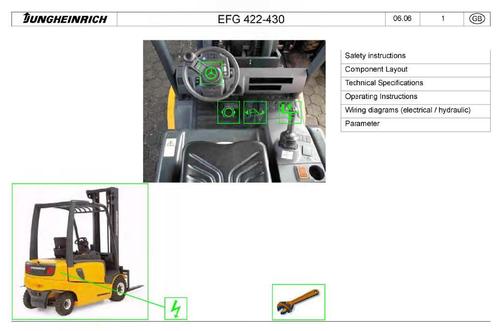
Safety instructions
Component Layout
Technical Specifications
Operating Instructions
Wiring diagrams (electrical / hydraulic)
Parameter
Minimum braking and braking distance measurement (see service manual D6360.03)
Guidelines for installing brake pipe lines (see service manual D 6360.16)
Parking brakes (see service manual D6360.21)
Wheel brake
-Multi Plates
Brake system
-Operating Brake
-Bleeding the brakes
-Check and release the spring-loaded brake
-Manual release of the spring-loaded brake
-Main brake cylinder (single stage) (See service manual GB 4001)
-Spring-loaded parking brake
-Spring loaded cylinder
-Notes on how to avoid accidents and material damage during maintenance, test and repair work on industrial trucks with electronic components (see service manual J 6900.09)
- Electrical system design
- Truck Block Diagram
Switches / Switch mechanism
-Contactors, charging contactor operation
Misc. Electrical
- Traction and lift controller functional description
- Basic Operation of Threephase Currents for Lift and Traction Drive Systems
- Replacing control system components up to 06.05 models
- Control system installation position
- Fuse Rating
-CANION installation position
-CANION function description
Wiring
- SOLO PILOT Connector Layout
- Pre- 06.05 Connector Layout
- Post- 06.05 Connector Layout
- Multi-Function Steering Wheel Connector Layout
Display
-Multi-function display (see SHB J 5003)
- Displays (see SHB J 5002)
- Error Logbook Representation
- Reset to its delivery status
- Service LISA from 06.05
- Design
- Commissioning with the Service LISA
- Parameter review
- Parameter settings
- Changing parameters
--- Lisa diagnosis mode up to 06.05 models
--- Lisa diagnosis mode from 06.05 models
- Drive system components
Electric motor
-Traction motor
---Speed sensor
---Sensor Bearing
Electrical
---Traction/lift controller functional and description
---Disassembly / Assembly of Traction - Lift Controller
Mech. Transmission
-Dismantling the drive unit
---Dismantling the drive axle
Wheels
- Drive wheel
Controls
-Travel switch/Accelerator pedal
Operator Position
-Armrest
Chassis and basic truck
-Auxiliary weight disassembly
Hydraulic system
- Pump motor / pump / pressure filter design
- For assembly, see service manual I 5006.
-SOLO PILOT pilot valve
-MULTI-PILOT pilot valve standard version
-Pilot valve default setting: SOLO-PILOT ; MULTI-PILOT; pressure limitation valve (see service manual I5005 )
Mast, mechanical
-Chains (for chain elongation testing see service manual G 6355.01)
-Mast rollers (lifting frame with inclined support rollers, see service manual G6233.01)
Load handler
- Forks (see service manual G1 6401 .01)
Mast tilt
-Cylinder
Electrical
- Sensors (Sensor bearing, see 004 014 293 00002)
Controls
- Control panel
Commissioning
-Commissioning (see Operating Instructions, Chapter C)
Maintenance
- Notes on how to avoid malfunctions and material damage when cleaning an industrial truck see service manual Z 0000.15
- Notes on how to avoid accidents and material damage during maintenance, test and repair work on industrial trucks with electronic components see service manual J 6900-09
- Regular safety inspection (at least annually)
- Maintenance checklist B
- Maintenance checklist C
- Maintenance checklist (cold store) B
- Maintenance checklist (cold store) C
Steering axle
- Steering axle design
Steering transmission
- Steer unit assembly / disassembly
Multifunction steering wheel
-Steer motor
Steering wheel
- Multifunction steering wheel
Mechanical components
- Steering column
Electrics
-Steering system block diagram
-Multifunction steering wheel block diagram
-Connection diagram for the multi-function steering wheel steering controller
-Steering angle sensor (for replacement/adjustment see service manual B 6001)
-Multifunction steering wheel steering controller
-RSC28 MH Angle Sensor
-Actual Value Sensor Assembly Position (3U9)
-Setpoint Sensor Assembly Position (3U10)
-Multi-function steering wheel steering controller
-Multi-function steering wheel actual value sensor (steering cylinder linear sensor)
File Data
This file is sold by belgreen, an independent seller on Tradebit.
| File Size | 91 megabytes |
| File Type |