$14.95
Download NowSold by belgreen on Tradebit
The world's largest download marketplace
3,252,412 satisfied buyers
The world's largest download marketplace
3,252,412 satisfied buyers

Komatsu Wheel Loader WA250PT-5H sn: WA250H60051 and up Operating and Maintenance Instructions
Original factory manuals for Komatsu Loaders, Dozers, Excavators contains high quality images, circuit diagrams and instructions to help you to operate, maintenance and repair your truck. All Manuals Printable, contains Searchable Text and Navigation Bookmarks
Covered models:
WA250PT-5H sn: WA250H60051 and up
Format: PDF, 255 Pages
Language: English
Contents:
FOREWORD
Foreword
Safety information
Introduction
Directions of machine
Necessary information
Machine serial Noplate and position
Engine serial Noplate and position
Position of service meter
Table to enter serial Noand distributor
Contents
Dimensions, weights and operating data
WA250PT-5H: Dimensions, weights and operating data
CE-conforming equipment
CE-conforming equipment
Manufacturer-supplied CE-conforming equipment, according to document 421-93-H1900
SAFETY
Safety labels
Location of safety labels
Presentation of safety labels
General precautions
Safety rules
Precautions for operation
Starting engine
Operation
Transportation
Battery
Towing
Precautions for maintenance
Safety instructions
Precautions with tires
Handling tires
Precautions when storing tires
OPERATION
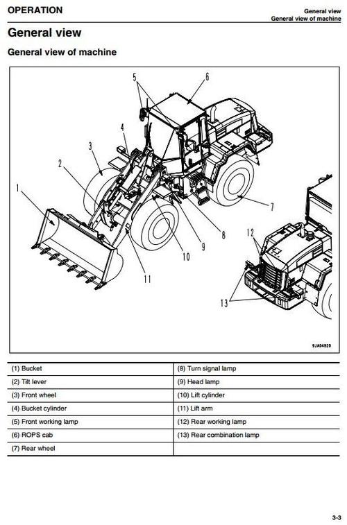
General view
General view of machine
General view of controls and gauges
Explanation of components
Machine monitor
Monitor system
Types of warning
Central warning lamp
Character display portion
Emergency stop item
Caution items
Warning/limit functions for travel speed
Inspection and maintenance item
Pilot display portion
Meter display portion
Other functions of machine monitor
Switches
Control levers, pedals
Steering tilt lock lever
Cap and cover with lock
Safety bar
Towing pin
Grease pump
Cab door inner lock
Cab door open lock
Cab window open lock cancel knob
Fuse
Fuse capacity and name of circuit
Slow blow fuse
Power outlet
Air conditioner
General locations and function of control panel
Method of operation
Precautions when using
Handling cab wiper
Preventing damage to wiper arm bracket
Operation
Check before starting engine, adjust
Walk-around check
Check before starting
Adjustment
Operations and checks before starting engine
Starting engine
Operations and checks after starting engine
Breaking-in the machine
Normal operation
Stopping engine
Moving the machine (Directional, speed), stopping the machine
Moving the machine
Changing direction
Stopping the machine
Turning
Emergency steering
Operation of work equipment
Handling hydraulic quick coupler
Installing the attachment
Removal and installation of the attachment
Precautions for use
Precautions when removing the attachment
Work possible using wheel loader
Digging operations
Leveling operations
Pushing operation
Load and carry operations
Loading operations
Precautions for operation
Permissible water depth
Fuel
Coolant
Grease
Carrying out KOWA (Komatsu Oil Wear Analysis)
Storing oil and fuel
Filters
Biodegradable hydraulic oil and lubricants
Outline of electric system
Wear parts
Wear parts list
Fuel, coolant and lubricants
Lubrication chart
Proper selection of fuel, coolant and lubricants
Standard tightening torques for bolts and nuts
Torque list
Periodic replacement of safety critical parts
Safety critical parts
Maintenance schedule chart
Service schedule
Service procedure
Initial 250 hours service (only after the first 250 hours)
When required
Check, clean, or replace air cleaner element
Dust pre-extractor "Turbo II": check, clean
Clean inside of cooling system
Check oil level in transfer case, add oil
Check axle oil level, add oil
Clean axle case breather
Clean air conditioner condenser
Check window washing fluid level, add fluid
Clean radiator fins and cooler fins
Clean transfer oil cooler fins
Check electrical intake air heater
Replace bolt on cutting edge
Replace bucket teeth
Check air conditioner
Replace slow blow fuse
Selection and inspection of tires
Check before starting
Every 50 hours service
Drain water, sediment from fuel tank
Every 100 hours service
Lubricate rear axle pivot pin
Clean element in air conditioner fresh air filter
Check oil level in hydraulic tank, add oil
Every 250 hours service
Check battery electrolyte level
Check parking brake
Check air conditioner compressor belt tension, adjust
Check for loose wheel hub bolts, tighten
Clean element in air conditioner recirculation filter
Lubricating
Every 500 hours service
Change oil in engine oil pan, replace engine oil filter cartridge
Replace fuel filter cartridge
Clean water separator strainer
Every 1000 hours service
Change oil in transfer case
Clean transfer case breather
Replace HST oil filter element
Lubricating
Check tightening parts of turbocharger
Check play of turbocharger rotor
Check alternator driving belt tension and replacement
Every 2000 hours service
Change oil in hydraulic tank, replace hydraulic filter element
Replace hydraulic tank breather element
Change axle oil
Replace element in air conditioner recirculation air filter, fresh air filter
Check alternator, starting motor
Check engine valve clearance, adjust
Check brake disc wear
Clean and check turbocharger
Check accumulator gas pressure
Check vibration damper
Every 4000 hours service
Lubricating
Check water pump
TECHNICAL DATA
Technical data
Noise emission levels
Vibration level
ATTACHMENTS, OPTIONS
Selecting bucket and tires
Handling fork tool
Explanation of components
Work equipment lever
Operation
Loading operation
Method of using 3 levers
Explanation of components
Lift arm control lever
Bucket control lever
Auxiliary control lever
Directional selector switch
Directional selector actuation switch
Operation
Using switch to change between forward and reverse
Central lubrication system
Operating the central lubrication system
Display and control unit
Led-display
Pushbuttons
Changing the lubrication interval times
INDEX
Index.
File Data
This file is sold by belgreen, an independent seller on Tradebit.
| File Size | 9 megabytes |
| File Type |