$24.00
Download NowSold by belgreen on Tradebit
The world's largest download marketplace
3,253,479 satisfied buyers
The world's largest download marketplace
3,253,479 satisfied buyers

Komatsu Crawler Dozers D61EX-23 sn:30001 and up, D61PX-23 sn:30001 and up Workshop Service Manual
Original factory manuals for Komatsu Loaders, Dozers, Excavators contains high quality images, circuit diagrams and instructions to help you to operate, maintenance and repair your truck. All Manuals Printable, contains Searchable Text and Navigation Bookmarks
Covered models:
D61EX-23 sn:30001 and up
D61PX-23 sn:30001 and up
Format: PDF, 1724 Pages
Language: English
Contents:
00 Index and foreword .
Index
Foreword, safety and general information
Important safety notice
How to read the shop manual
Explanation of terms for maintenance standard
Handling equipment of fuel system devices
Handling of intake system parts
Handling of hydraulic equipment
Method of disconnecting and connecting of push-pull type coupler
Handling of electrical equipment
How to read electric wire code
Precautions when performing operation
Practical use of KOMTRAX
Standard tightening torque table
List of abbreviation
Conversion table
01 Specification.
Table of contents
Specifications
Specification drawing
Specifications
Weight table
Table of fuel, coolant, and lubricants
10 Structure and function .
Table of contents
Engine and cooling system
Engine related parts
KVGT
EGR system piping drawing
EGR system circuit diagram
EGR valve
EGR cooler
KCCV layout drawing
KCCV ventilator
KDPF
Cooling system
Cooling fan motor
Oil cooler bypass and HST charge safety valve
Power train
Power train system
Damper
Hydraulic component layout of HST
Steering and brake control
HST pump
HST motor
Charge pump
Solenoid valve
Final drive
Undercarriage and frame
Main frame
Suspension
Track frame and idler cushion
Hydraulic system
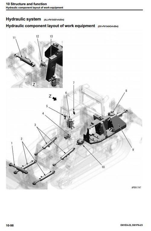
Hydraulic component layout of work equipment
Work equipment control system
Hydraulic tank
CLSS
Work equipment and cooling fan pump
Control valve
Ripper PPC valve
Quick drop valve
Angle control EPC valve
Accumulator
Work equipment
Blade
Ripper
Piston valve
Cab and its attachments
ROPS cab
Cab mount
Electrical system
Engine control system
Cooling system control system
HST control system
Parking brake control system
System operating lamp function
Battery disconnect switch function
Machine monitor system
KOMTRAX system
System component parts
Sensor
20 Standard value tables
Table of contents
Standard service value table
Standard value table for engine
Standard value table for machine
Standard value table for electrical system
30 Testing and adjusting
Table of contents
Related information on testing and adjusting
Tools for testing and adjusting
Sketch of tools for testing and adjusting
Engine and cooling system
Testing engine speed
Testing boost pressure
Testing exhaust gas color
Testing and adjusting valve clearance
Testing compression pressure
Testing blowby pressure
Testing engine oil pressure
Testing EGR valve and KVGT oil pressures
Testing fuel pressure
Testing fuel discharge, return and leakage
Bleeding air from fuel system
Testing fuel circuit for leakage
Handling cylinder cutout mode operation
Handling no-injection cranking operation
Testing of KDPF and muffler stack for looseness and damage
Testing of installed condition of cylinder heads and manifolds
Testing engine piping for damage and looseness
Replacing alternator belt
Power train
Testing and adjusting HST oil pressure
Testing output pressure of solenoid valve
Testing if machine travels straight
Simple test procedure for brake performance
Adjusting deceleration/brake pedal
Adjusting parking brake lever
Move disabled machine urgently
Undercarriage and frame
Adjusting idler clearance
Checking sprocket wear
Testing and adjusting track tension
Hydraulic system
Releasing remaining pressure in work equipment cylinder
Testing and adjusting work equipment oil pressure
Testing source pressure of control circuit
Testing outlet pressure of work equipment EPC valve and fan EPC valve
Isolating the parts causing hydraulic drift in blade and ripper
Testing internal oil leakage of work equipment cylinder
Testing fan speed
Testing fan circuit oil pressure
Bleeding air from hydraulic circuit
Work equipment
Adjusting work equipment lock lever
Adjusting play of blade center ball
Electrical system
Special functions of machine monitor
Adjustment method when HST controller has been replaced
Adjustment method when electric or hydraulic device has been replaced
Adjusting rearview camera angle
Handling voltage circuit of engine controller
Handling battery disconnect switch
Testing diodes
Pm clinic
Pm Clinic service
Pm Clinic check sheet
40 Troubleshooting
Table of contents
Related information on troubleshooting
Troubleshooting points
Sequence of events in troubleshooting
Checks before troubleshooting
Inspection procedure before troubleshooting
Preparation for troubleshooting of electrical system
Classification and procedures for troubleshooting
Symptom and troubleshooting numbers
Information in troubleshooting table
Procedure for troubleshooting wiring harness of pressure sensor system for open circuit
Connector list and layout
Connector contact identification
T-branch box and T-branch adapter table
Fuse location table
Precautions for KDPF (KCSF and KDOC) Cleaning and Replacement
Preparation of dummy temperature sensor (for KDOC and KDPF temperature sensors)
Preparation of short circuit electrical connector (for failure codes [CA1883] and [CA3135])
Failure codes table
Troubleshooting by failure code (Display of code)
Troubleshooting of electrical system (E-mode)
Troubleshooting of hydraulic and mechanical system (H-mode)
Information described in troubleshooting table (H-mode)
System chart of hydraulic and mechanical systems
Failure mode and cause table
Troubleshooting of engine (S-mode)
Information described in troubleshooting table (S mode)
50 Disassembly and assembly .
Table of contents
Related information on disassembly and assembly
How to read this manual
Coating materials list
Special tools list
Sketches of special tools
Engine and cooling system
Power train
Undercarriage and frame
Separation and connection of track shoe assembly (Standard type track shoe)
Separation and connection of track shoe assembly (PLUS type track shoe)
Overall disassembly and assembly of track shoe assembly (Standard type track shoe)
Overall disassembly and assembly of track shoe assembly (PLUS type track shoe)
Hydraulic system
Work equipment
Cab and its attachments
Electrical system
60 Maintenance standard
Table of contents
Engine and cooling system
Engine mount
Cooling fan motor
Oil cooler bypass and HST charge safety valve
Power train
Damper
HST pump
HST motor
Charge pump
Solenoid valve
Final drive
Sprocket
Full-scale drawing of sprocket tooth profile
Undercarriage and frame
Suspension
Track frame and idler cushion
Idler
Track roller
Carrier roller
Track shoe
Hydraulic system
Hydraulic tank
Work equipment and cooling fan pump
Control valve
Ripper PPC valve
Quick drop valve
Angle control EPC valve
Work equipment
Blade
Cutting edge and end bit
Ripper
Lift cylinder
Tilt cylinder
Angle cylinder
Ripper cylinder
Cab and its attachments
Cab mount
Electrical system
Electric steering lever
80 Appendix.
Table of contents
Air conditioner components
Precautions for refrigerant
Air conditioner component
Configuration and function of refrigeration cycle
Outline of refrigeration cycle
Air conditioner unit
Dual pressure switch
Pressure switch
Compressor
Condenser
Receiver drier
Procedure for testing and troubleshooting
Electrical circuit diagram
System diagram
Parts and connectors layout
Testing relays
Troubleshooting chart 1
Troubleshooting chart 2
Information described in troubleshooting table
A-1 Troubleshooting for condenser fan
A-2 Troubleshooting for compressor and refrigerant system (Air is not cooled)
A-3 Troubleshooting for blower motor system (No air comes out or air flow is
abnormal)
A-4 Troubleshooting for temperature control
Troubleshooting with gauge pressure
Connection of service tool
Precautions for disconnecting and connecting hoses and tubes in air conditioner
circuit
Handling of compressor oil
90 Diagrams and drawings.
Table of contents
Hydraulic circuit diagram
Symbols in hydraulic circuit diagram
Hydraulic circuit diagram
Electric circuit diagram
Symbols in electric circuit diagram
Electrical circuit diagram
Index.
File Data
This file is sold by belgreen, an independent seller on Tradebit.
| File Size | 47 megabytes |
| File Type |