$14.95
Download NowSold by belgreen on Tradebit
The world's largest download marketplace
3,251,781 satisfied buyers
The world's largest download marketplace
3,251,781 satisfied buyers

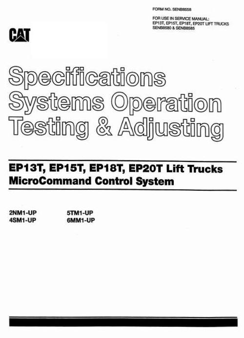
CAT Electric Forklift Truck Microcommand Control System EP13T, EP15T, EP18T, EP20T Workshop Service Manual
Original factory manuals for CAT Lift Trucks contains high quality images, circuit diagrams and instructions to help you to operate, maintenance and repair your truck. All Manuals Printable, without restrictions, contains Searchable Text and bookmarks
Covered models:
EP13T (2NM1-up)
EP15T (4SM1-up)
EP18T (5TM1-up)
EP20T (6MM1-up)
Format: PDF, 111 Pages
Language: English
Contents:
Specifications
Component Measurements
Console
Contactors
Control Panel
Current Measurements
DirectionSwitch
Fuses
HeadCapacitor
Horn
Instrument Panel .
LED Display Layout
Logic Board Layout
Thermal Switch
Transistor Connections
Transistor Measurements
Systems Operation
Accessory Circuits
DC-DC Converter
HornCircuit
Hour Meter Circuit
Actuation Circuit .
Drive Circuit
Bypass Operation
ControlCircuit Operation
Current Limit ,
ElectricalBraking(Plugging) Operation
Failure ProtectionCircuit
FlybackCircuit
Power Circuit Operation
Thermal ProtectionCircuit
General Information
Glossary
Hydraulic Circuit
Pump ControlCircuit Operation
Pump Power Circuit Operation
LiftTruckTurning Operation
Locationof Control Panel Components
Logic Unit
OperationalCircuit Elements ..
Accelerator Control
Battery Discharge Indicator (BDI)
Chat Mode
LED Display
Life Interrupt
On Board "Run Time" Diagnostics (Fault Detection)
Steer Angle Sensor
PowerSteeringCircuit
Programmable Features
Activating DefaultSettings
ProgrammingFeatures
Symbol Library
Testing and Adjusting
Accessing Stored Faults
System Tests andAdjustments
ComponentTests
Accelerator Control
Capacitor (Head)
Conductor and Switch Continuity
Contactor
Contactor (By passActivation)
DC-DC Converter
DiodeReplacement
Diodes
Display (LED) .
Driver Board(Off Vehicle)
Driver Board(OnVehicle)
Lift Switch
Logic Unit Quick ReferenceVoltage Check
Resistors (R302 and R312)
Steer Angle Sensor
Thermal Switch
Transistor (1TRN)
Transistor Replacement (1TRN)
Discharging HeadCapacitor (HEAD CAP)
ElectricalSystemAdjustments
Accelerator Control Linkage
Lift Switch
Parking BrakeSwitch
Logics Removal
RapidTune-Up Procedure
Final Logic BoardAdjustments
Battery Discharge Indicator (BDI) Adjustment
Current Limit Test andAdjustment
ElectricalBraking(Plugging) Current Test
andAdjustment
"RunTime" Tests
ControlPanelOvertemperature Protection
Failure Protection
Key to ON, No Operator Warning,
Display = "E" (Flashing)
Static Returnto OFF (SRO)
Steer Angle Sensing
Test Equipment
Troubleshooting
Built-inDiagnosticOperation
Control and Power System Operational Checks
PreparationTests and Checks
Troubleshooting Problem List
Troubleshooting Check List
REFERENCE: For the MicroCommand Control System
Schematics , refer to Form https://www.tradebit.comB8454-01 or SENB8366-01 .
File Data
This file is sold by belgreen, an independent seller on Tradebit.
| File Size | 17 megabytes |
| File Type |
