$44.00
Download NowSold by thetechman on Tradebit
The world's largest download marketplace
3,252,959 satisfied buyers
The world's largest download marketplace
3,252,959 satisfied buyers

Rohde and Schwarz UPA English Operating Manual
Operation manual ONLY! English version.
Scanned at 300x300dpi grayscale.
220 pages
Contents
2 Operation
2.1 Explanation of the Controls
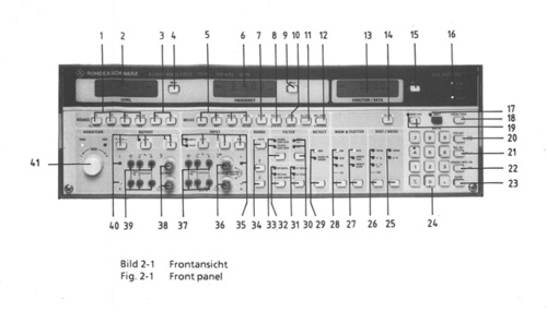
2.1.1 Front Panel, Fig. 2-1
2.1.2 Rear Panel, Fig. 2-2
2.2 Preparations for Use
2.2.1 Setting Up the Instrument
2.2.2 Rack Mounting
2.2.2.1 Retrofit of the Input/Output Connectors to the Rear Panel
2.2.3 Power Supply
2.2.4 Switching On
2.2.4.1 Adjusting the Brightness of the LCDs
2.2.5 Connection of Other Instruments in Series
2.2.5.1 Connection of Balanced-to-Ground Devices
2.2.5.2 Connection of Unbalanced-to-Ground Devices
2.2.5.3 Connection of an External Filter
2.2.5.4 Connection to the AC Voltage Output
2.2.5.5 Connection to the DC Voltage Outputs (Option UPA-B1)
2.2.5.6 Connection to the I EC-bus Interface
2.3 Manual Operation
2.3.1 Measurement Section
2.3.1.1 Operating Mode/Channel Settings of the Measurement Section
2.3.1.1.1 Measurements on Balanced-to-Ground Voltage Sources
2.3.1.1.2 Permissible Voltages at the Inputs a/b
2.3.1.1.3 Measurements on Unbalanced Voltage Sources
2.3.1.1.4 Permissible Voltages at the Inputs c
2.3.1.2 Switching On the Autoranging Function
2.3.1.3 Holding the Current Range and Manual Range Selection
2.3.1.4 Filters
2.3.1.4.1 Weighting Filters SOUND to CCIR and TELEPHONE to CCITT
2.3.1.4.2 Highpass Filter
2.3.1.4.3 Lowpass Filter
2.3.1.4.4 Bandpass Filter to CCIR for Unweighted Noise Measurements
2.3.1.4.5 Spezia! Filters (Options UPA-B2 and UPA-B3)
2.3.1.4.6 Input of the Special Filter Numbers
2.3.1.4.7 Recalling the Selected Special Filter Number
2.3.1.4.8 External Filter
2.3.1.5 Selecting the Rectifier Circuit
2.3.1.6 Level and Frequency Measurements
2.3.1.6.1 Level Display of Input Signal without Reference
2.3.1.6.2 Level Display of Input Signal with Reference
2.3.1.6.3 Frequency Display of Input Signal without Reference
2.3.1.6.4 Frequency Display of Input Signal with Reference
2.3.1.6.5 Reference Value Input via the Keyboard
2.3.1.6.6 Transfer of Displayed Value as Reference Value
2.3.1.6.7 Recalling the Current Reference Level
2.3.1.6.8 Recalling the Current Reference Frequency
2.3.1.6.9 Input of Impedance for dBm and W Display
2.3.1.6.10 Recalling the Current Impedance Value
2.3.1.6.11 Measuring Speed
2.3.1.7 DC Measurement
2.3.1.8 Phase Measurement
2.3.2 Generator Unit (Option UPA-B6)
2.3.2.1 Operating Mode/Channel Setting of Generator
2.3.2.1.1 Enter and Recall the Output Impedance
2.3.2.1.2 Balanced-to-Ground Generator Output
2.3.2.1.3 Unbalanced-to-Ground Generator Output
2.3.2.1.4 Overload Protection and Input Protection
2.3.2.2 Frequency Setting of Generator
2.3.2.2.1 Frequency Entry via the Keyboard
2.3.2.2.2 Linear Variation of Frequency After Switching On the UPA
2.3.2.2.3 Logarithmic Variation of Frequency
2.3.2.2.4 Variation of Frequency in Octave and Third-octave Sequences to DIN 45401
2.3.2.3 Level Setting of the Generator
2.3.2.3.1 Level Input via the Keyboard
2.3.2.3.2 Linear Variation of the Level After Switching On the UPA
2.3.2.3.3 Logarithmic Variation of the Level
2.3.2.4 Random Level and Frequency Sequence (RANDOM Sequence)
2.3.2.5 Recalling the Frequency or Level Step Size of the Spinwheel
2.3.2.6 Sweep
2.3.2.6.1 Entry of Parameters for NORMAL Sweep
2.3.2.6.2 Entry of Parameters for Random Sweep
2.3.2.6.3 Sweep Direction
2.3.2.6.4 Sweep Mode
2.3.2.6.5 Sweep Start
2.3.2.6.6 Sweep Halt
2.3.2.6.7 Sweep Continue
2.3.2.6.8 Sweep Abort
2.3.2.6.9 Synchronization of the Sweep with the Measuring Loop
2.3.2.7 Limitation of Generator Range
2.3.2.8 Logging of Measured Values via the IEC-bus Interface
2.3.2.8.1 Print and Plot Mode
2.3.2.8.2 Input of Scaling Values
2.3.2.8.3 Input of Reference Lines
2.3.2.8.4 Possible Choices for Form Feed
2.3.2.8.5 Display of Function Curve Only
2.3.2.8.6 Display or Suppression of Reference Lines
2.3.2.8.7 Add Complete UPA Setting to Test Log
2.3.2.8.8 Reference Range Identification
2.3.2.8.9 Function Curve Assignment for RANDOM Sweep with Simultaneous Change in Level and Frequency
2.3.3 Function Unit
2.3.3.1 WOW & FLUTTER-Measurements (Option UPA-89)
2.3.3.1.1 2-sigma Test Method for Wow & Flutter Measurements
2.3.3.2 Distortion Factor Measurements (Option UPA-B8)
2.3.3.2.1 Switchover to Display Units , dB, Volts, A, AdB
2.3.3.2.2 Distortion Measurement TOTAL
2.3.3.2.3 Distortion Measurement 3*fo and n*fo
2.3.3.2.4 Distortion Measurement with Combinations of Harmonics (THD)
2.3.3.2.5 Recalling of the Ordinal Number of the Distortion Measurement
2.3.3.2.6 Presetting Frequency for Distortion Measurements
2.3.3.2.7 Measuring Distortion Factors 71 or SINAD Values 3 dB
2.3.3.2.8 Increasing the Distortion Measuring Speed
2.3.3.3 SINAD and Signal/Noise Measurements
2.3.3.3.1 SINAD Measurements
2.3.3.3.2 S/N Measurements
2.3.4 Entering Numbers via the Keyboard
2.3.5 Display Settings
2.3.5.1 Digital Display
2.3.5.2 Analog Display in Bar Form
2.3.5.3 Digital Display Combined with Analog Display
2.3.6 Complete Instrument Settings
2.3.6.1 Storing Complete Instrument Settings
2.3.6.2 Recalling the Complete Instrument Settings
2.3.6.3 Write Protection for Complete Instrument Settings
2.3.7 DC Outputs (Option UPA-B 1)
2.3.7.1 Scale of Reference-based Level Display in AV oder AW
2.3.7.2 Scale of Reference-based Frequency Display in A Hz
2.3.7.3 Scale of Measured Function Values in and A
2.3.7.4 Scale of Level Units in dBV, dBm, dB
2.3.7.5 Scale of Measured Function Values https://www.tradebit.com oder AdB
2.3.7.6 Scale of Level Units in V, W
2.3.7.7 Linear or Logarithmic Scale of Frequency
2.3.7.8 Linear or Logarithmic Scale of Frequency Offset Of
2.3.7.9 Scale of Distortion Level in V or of Phase Angle in Degree
2.3.8 AC Output
2.3.9 Special Functions
2.3.9.1 Input of Special Functions
2.3.9.2 Display of the Active Special Functions
2.3.10 Setting Following Switch-on of UPA
2.3.11 Error Messages
2.3.12 Notes and Warnings
2.4 Control via IEC Bus
2.4.1 Setting the Device Address / Talk-Only
2.4.2 Recalling the Device Address
2.4.3 Interface Functins
2.4.4 Device-specific IEC-bus Commands
2.4.5 General Information on the IEC-Bus Command Syntax
2.4.6 Basic Setting
2.4.7 Measurement Section Commands
2.4.7.1 Setting the Channel
2.4.7.2 Setting the Filter
2.4.7.3 Setting the Operating Mode AC or DC and the Output Unit for Level and Frequency
2.4.7.4 Setting the Rectifier
2.4.7.5 Setting the Measuring Range for Level Measurement
2.4.7.6 Setting the Measuring Speed
2.4.7.7 Setting the Display Mode for Level and Frequency
2.4.7.8 Storage and Recall of Reference Values
2.4.8 Function Commands
2.4.8.1 Setting the Output Unit for Function Measurement
2.4.8.2 Setting the Measuring Range for Wow & Flutter Measurement
2.4.8.3 Setting the Display Mode for Function Measurement
2.4.8.4 Setting the Function Measurement Wow & Flutter
2.4.8.4.1 Recall of Measurement Result of 2-sigma Background Measurement
2.4.8.5 Setting the Distortion Factor Measurement
2.4.8.6 Setting the Noise Measurement
2.4.8.6.1 SINAD Measurement
2.4.8.6.2 S/N Measurement
2.4.8.7 Storage and Recall of Reference Values
2.4.8.8 Phase Measurement
2.4.9 Generator Commands
2.4.9.1 Setting the Generator Output Channels
2.4.9.2 Setting the Generator Level and Generator Frequency
2.4.9.3 Setting the Range Limitation of the Generator
2.4.9.4 Conversion of Generator Level Values to dBm
2.4.9.5 Set Generator Output Impedance
2.4.9.6 Setting and Triggering the Generator Increment
2.4.9.7 Generator Sweep
2.4.9.8 Storage and Recall of Generator Impedance Value
2.4.9.9 Recall of Generator Setting Values
2.4.10 Sweep Commands
2.4.10.1 Setting the Sweep Parameters
2.4.10.2 Sweep Enable
2.4.10.3 Sweep Halt or Continue
2.4.10.4 Sweep Commands in Combination with Other Setting Commands
2.4.11 Commands for AC and DC Outputs
2.4.12 Interface Commands
2.4.12.1 Setting the Delimiter
2.4.12.2 Setting the SRQ Mode
2.4.12.3 Setting the Value Output
2.4.13 STORE/RECALL Commands for Complete Instrument Settings
2.4.14 Trigger Commands
2.4.14.1 Setting the Trigger Facilities for Output
2.4.14.2 Trigger Commands
2.4.15 Calibration Commands
2.4.16 IEC-bus Inquiry Commands
2.4.17 Service Request
2.4.17.1 Parallel Poll
2.4.17.2 Serial Poll
2.4.18 Measured Value Output in Talk Only Mode
2.4.19 Data Output
2.4.19.1 Text String Output
2.4.19.2 Data Output in Measuring Mode
2.4.19.3 Measurement Speeds
2.4.20 Addressed and Universal Commands
2.4.20.1 Device Clear
2.4.20.2 Selected Device Clear
2.4.20.3 Device Trigger
2.4.20.4 Local Lockout (Lock Manual Operation)
2.4.20.5 Go to Local (Switch to Manual Operation)
2.5 Installation of Options
File Data
This file is sold by thetechman, an independent seller on Tradebit.
| File Size | 113 megabytes |
| File Type |