$16.95
Download NowSold by maxxtor on Tradebit
The world's largest download marketplace
3,252,177 satisfied buyers
The world's largest download marketplace
3,252,177 satisfied buyers

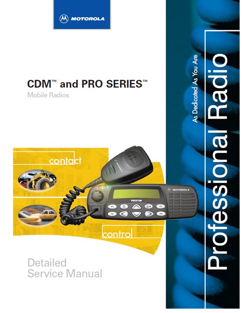
Motorola CDM and Pro series radio service manual
Chapter 1 Introduction
1 1 Scope of Manual
1 2 Warranty and Service Support
1 2 1 Warranty Period
1 2 2 Return Instructions
1 2 3 After Warranty Period
1 3 Related Documents
1 4 Technical Support
1 5 Warranty and Repairs
1 6 Radio Model Chart and Specifications
1 7 Radio Model Information
Chapter 2 Theory of Operation
2 1 Overview
2 2 Controller Section
2 2 1 Radio Power Distribution
2 2 2 Automatic On/Off
2 2 3 Emergency
2 2 4 Mechanical On/Off
2 2 5 Ignition
2 2 6 Microprocessor Clock Synthesizer
2 2 7 Serial Peripheral Interface (SPI)
2 2 8 SBEP Serial Interface
2 2 9 General Purpose Input/Output
2 2 10 Normal Microprocessor Operation
2 2 11 Static Random Access Memory (SRAM)
2 3 Controller Board Audio and Signalling Circuits
2 3 1 Audio Signalling Filter IC with Compander (ASFIC CMP)
2 3 2 Transmit Audio Circuits
2 3 3 Microphone Input Path
2 3 3
2 3 3
2 3 3
2 3 4 Transmit Signalling Circuits
2 3 4
2 3 4
2 3 4
2 3 5 Receive Audio Circuits
2 3 5
2 3 5
2 3 5
2 3 5
2 3 5
2 3 5
ii
2 3 5
2 3 6 Receive Signalling Circuits
2 3 6
2 3 6
2 3 6
2 4 UHF (403-470 MHz) Receiver Front-End
2 4 1 Front-End Band-Pass Filters & Pre-Amplifier
2 4 2 First Mixer and 1st Intermediate Frequency (IF)
2 4 3 2nd Intermediate Frequency (IF) and Receiver Back-End
2 5 Transmitter Power Amplifier (PA) 40 W
2 5 1 Power Controlled Stage
2 5 2 Pre-Driver Stage
2 5 3 Driver Stage
2 5 4 Final Stage
2 5 5 Bi-Directional Coupler
2 5 6 Antenna Switch
2 5 7 Harmonic Filter
2 5 8 Power Control
2 6 Frequency Synthesis
2 6 1 Reference Oscillator
2 6 2 Fractional-N Synthesizer
2 6 3 Voltage Controlled Oscillator (VCO)
2 6 4 Synthesizer Operation
2 7 VHF (136-174MHz) Receiver Front-End
2 7 1 Front-End Band-Pass Filters and Pre-Amplifier
2 7 2 First Mixer and 1st Intermediate Frequency (IF)
2 7 3 2nd Intermediate Frequency (IF) and Receiver Back-End
2 8 Transmitter Power Amplifier (PA) 45 W
2 8 1 Power Controlled Stage
2 8 2 Pre-Driver Stage
2 8 3 Driver Stage
2 8 4 Final Stage
2 8 5 Directional Coupler
2 8 6 Antenna Switch
2 8 7 Harmonic Filter
2 8 8 Power Control
2 9 Frequency Synthesis
2 9 1 Reference Oscillator
2 9 2 Fractional-N Synthesizer
2 9 3 Voltage Controlled Oscillator (VCO)
2 9 4 Synthesizer Operation
2 10 Control Head (PRO3100, CDM750)
2 10 1 Power Supplies
2 10 2 Power On/Off
2 10 3 Microprocessor Circuit
2 10 4 SBEP Serial Interface
2 10 5 Keypad Keys
2 10 6 Status LED and Back Light Circuit
2 10 7 Microphone Connector Signals
2 10 8 Speaker
2 10 9 Electrostatic Transient Protection
2 11 Control Head (PRO5100, PRO7100, CDM1250, CDM1550)
2 11 1 Power Supplies
2 11 2 Power On / Off
iii
2 11 3 Microprocessor Circuit
2 11 4 SBEP Serial Interface
2 11 5 Keypad Keys
2 11 6 Status LED and Back Light Circuit
2 11 7 Liquid Crystal Display (LCD)
2 11 8 Microphone Connector Signals
2 11 9 Speaker
2 11 10 Electrostatic Transient Protection
Chapter 3 Maintenance
3 1 Introduction
3 2 Preventive Maintenance
3 2 1 Inspection
3 2 2 Cleaning
3 3 Safe Handling of CMOS and LDMOS
3 4 General Repair Procedures and Techniques
3 5 Recommended Test Tools
3 6 Transmitter Troubleshooting Chart
3 7 Receiver Troubleshooting Charts
3 8 Synthesizer Troubleshooting Charts
3 9 VCO Troubleshooting Charts
Chapter 4 Schematic Diagrams, Overlays, and Parts Lists
4 1 Introduction
4 1 1 Notes For All Schematics and Circuit Boards
List of Figures
2-1 Controller Block Diagram
2-2 DC Power Distribution Block Diagram
2-3 Transmit Audio Paths
2-4 Transmit Signalling Paths
2-5 Receive Audio Paths
2-6 Receive Signalling Paths
2-7 UHF Receiver Block Diagram
2-8 UHF Transmitter Block Diagram
2-9 UHF Synthesizer Block Diagram
2-10 UHF VCO Block Diagram
2-11 VHF Receiver Block Diagram
2-12 VHF Transmitter Block Diagram
2-13 VHF Synthesizer Block Diagram
2-14 VHF VCO Block Diagram
4-1 PRO3100/CDM750 Control Head Top Overlay
4-2 PRO3100/CDM750 Control Head Bottom Overlay
4-3 PRO3100CDM750 Control Head Schematic Diagram, Sheet 1
4-4 PRO3100CDM750 Control Head Schematic Diagram, Sheet 2
iv
4-5 PRO5100/PRO7100/CDM1250/CDM1550 Control Head Top
Overlay
4-6 PRO5100/PRO7100/CDM1250/CDM1550 Control Head Bottom
Overlay
4-7 PRO5100/PRO7100/CDM1250/CDM1550 Control Head
Schematic Diagram
4-8 PRO5100/PRO7100/CDM1250/CDM1550 Control Head Keypad
Schematic Diagram
4-9 PRO5100/PRO7100/CDM1250/CDM1550 Control Head LCD
Schematic
4-10 PRO5100/PRO7100/CDM1250/CDM1550 Control Head Display
Schematic
4-11 Complete Controller Schematic Diagram
4-12 Controller Control Schematic Diagram
4-13 Controller I/O Schematic Diagram
4-14 Controller Audio Schematic Diagram
4-15 Controller Supply Voltage Schematic Diagram
4-16 UHF (403-470MHz) Voltage Controlled Oscillator Schematic Diagram
4-17 UHF (403-470MHz) Fractal-N Schematic Diagram
4-18 UHF (403-470MHz) Power Amplifier Schematic Diagram
4-19 VHF (136-174MHz) Main Board Top Side PCB
4-20 VHF (136-174MHz) Receiver Front End Schematic Diagram
4-21 VHF (136-174MHz) Receiver IF Schematic Diagram
4-22 VHF (136-174MHz) Fractal-N Schematic Diagram
4-23 VHF (136-174MHz) Voltage Controlled Oscillator Schematic Diagram
4-24 VHF (136-174MHz) Power Amplifier Schematic Diagram
List of Tables
1-1 Radio Model Number
3-1 Recommended Test tools
4-1 PRO3100/CDM750 Control Head Parts List
4-2 PRO5100/PRO7100/CDM1250/CDM1550 Control Head Parts List
4-3 Controller Parts List
4-4 UHF B1 Radio Parts List
4-5 VHF (136-174MHz) Radio Parts List
File Data
This file is sold by maxxtor, an independent seller on Tradebit.
| File Size | 2 megabytes |
| File Type |
